Flapping and rotating machine
A technology of flapping rotorcraft and flapping rotor, which is applied to rotorcraft, helicopters, motor vehicles, etc., can solve the problems of low efficiency, poor lift stability, and poor flight flexibility of flapping rotorcraft, so as to improve efficiency, avoid drag, The effect of improving stability
- Summary
- Abstract
- Description
- Claims
- Application Information
AI Technical Summary
Problems solved by technology
Method used
Image
Examples
Embodiment 1
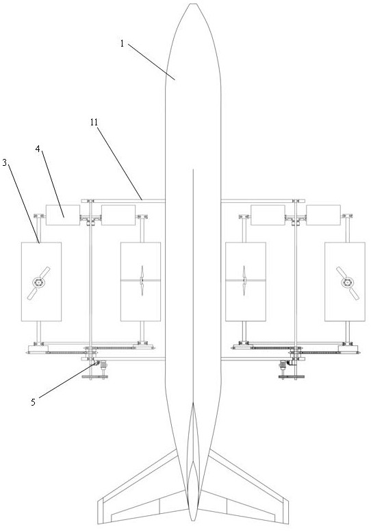
[0139] The embodiment of the present invention discloses a flapping rotor, comprising: a fuselage 1, a flapping rotor 3 and a controller;
[0140] The tail of the fuselage 1 is provided with an empennage or a tail rotor, the belly is provided with a landing gear, and both sides are symmetrically fixed with flapping rotors;
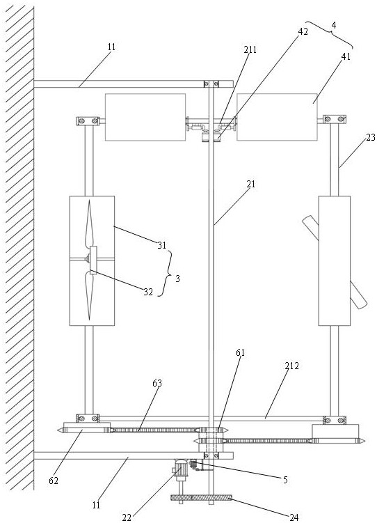
[0141] The flapping rotor 3 includes: a revolution main shaft 21, a revolution motor 22, a revolution transmission gear set 24, an autorotation transmission, an autorotation main shaft 23 and a rotor mechanism 30;
[0142] The revolving main shaft 21 is arranged on both sides of the fuselage 1 through the flapping rotor bracket 11, and is rotatably connected with the flapping rotor bracket 11 through a bearing, and its axial centerline is parallel to the axial centerline of the fuselage 1, while the revolving main shaft 21 The front and rear rotating arms 211 and 212 are vertically fixed respectively at both ends, and the front rotating arm 211 and the rea...
Embodiment 2
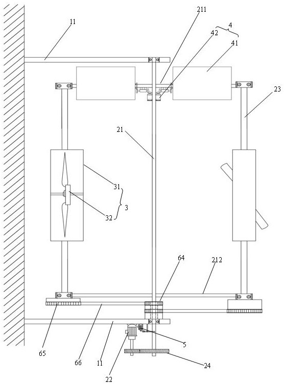
[0154] Embodiment 2 of the present invention is different from Embodiment 1 in that: the rotation transmission device is a synchronous belt transmission mechanism, and the synchronous belt transmission mechanism includes two identical central synchronous wheels 64, transmission synchronous wheels 65 and synchronous belts 66, and the central synchronous wheel 64 The diameter ratio with the transmission synchronous wheel 65 is 1:2;
[0155] The end faces of two central synchronous wheels 64 are parallel and fixed, while the end faces of one of them central synchronous wheels 64 are fixed on the flapping rotor support 11, and the centers of the two central synchronous wheels 64 are provided with diameters greater than the through holes of the revolving main shaft 21 as turning space;
[0156] The two transmission synchronous wheels 65 are respectively fixed on the two rotation main shafts 23 in one-to-one correspondence, and the two central synchronous wheels 64 are connected to ...
Embodiment 3
[0158] Embodiment 3 of the present invention is different from Embodiment 1 in that: the rotation transmission device is a chain transmission mechanism, and the chain transmission mechanism includes two identical first driving bevel gears 67, second driven bevel gears 68 and torque transmission mechanisms, one of which The end faces of the first driving bevel gears 67 are fixed on the flapping rotor bracket 11, and the centers of the two first driving bevel gears 67 are provided with a through hole with a diameter larger than the revolution main shaft 21 as a rotating space;
[0159] The two second driven bevel gears 68 are respectively fixed on the two self-rotating main shafts 23 in one-to-one correspondence, and the two first driving bevel gears 67 are connected to the two second driven bevel gears 68 in one-to-one correspondence through a torque transmission mechanism. ;
[0160] The torque transmission mechanism comprises a first transmission shaft 691, a first driven bev...
PUM
 Abstract
Description
Claims
Application Information
 - R&D
- Intellectual Property
- Life Sciences
- Materials
- Tech Scout
- Unparalleled Data Quality
- Higher Quality Content
- 60% Fewer Hallucinations
Browse by: Latest US Patents, China's latest patents, Technical Efficacy Thesaurus, Application Domain, Technology Topic, Popular Technical Reports.
© 2025 PatSnap. All rights reserved.Legal|Privacy policy|Modern Slavery Act Transparency Statement|Sitemap|About US| Contact US: help@patsnap.com


