Mechanical breaking demolition method for low-rise building

A construction and machinery technology, applied in the field of mechanized crushing and demolition of low-rise buildings, can solve problems such as difficulty in platform construction, save construction costs and labor costs, improve demolition efficiency, and save resources.

Inactive Publication Date: 2021-03-02
CHINA RAILWAY 11TH BUREAU GRP
View PDF4 Cites 6 Cited by
  • Summary
  • Abstract
  • Description
  • Claims
  • Application Information

AI Technical Summary

Problems solved by technology

[0005] The invention provides a method for mechanized crushing and demolition of low-rise buildings, which solves the problem of difficulty in building platforms existing in existing mechanized crushing and demolition buildings

Method used


Image

  • Mechanical breaking demolition method for low-rise building
  • Mechanical breaking demolition method for low-rise building
  • Mechanical breaking demolition method for low-rise building

Examples


Embodiment 1

[0039] Embodiment one demolition single-family low-rise building

[0040] Taking the demolition of a high school library as an example, the construction method of the first embodiment will be described.
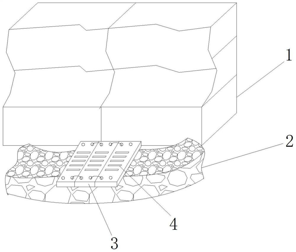
[0041] The building 1 has an area of ​​3150㎡ and is a 3-storey brick-concrete frame structure. The construction project is located in the bustling road section of the city, and the surrounding environment in the school is complicated, so it cannot be demolished by blasting; The construction efficiency of the division method is low, the construction cost is high, and the construction period is extremely tight, and manual demolition cannot meet the requirements; ordinary mechanized crushing and demolition requires the construction of a platform and the cooperation of large cranes, etc., resulting in increased workload and increased construction costs, and it is close to other teaching buildings. Unable to build platform. In order to save costs and reduce construction difficult...

Embodiment 2

[0051] Embodiment two demolition of adjacent buildings

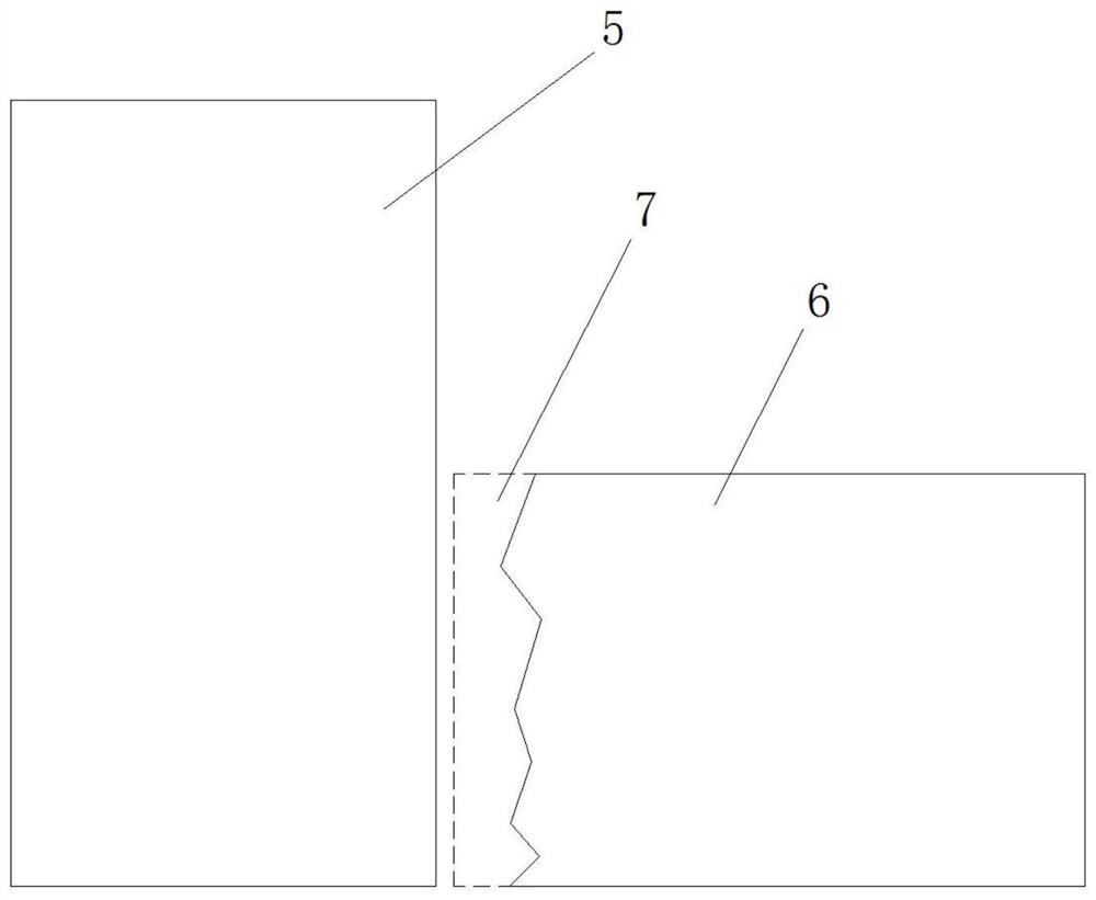
[0052] When demolishing one of the lower buildings 6 in the two adjacent buildings at an interval of 0-100cm, the above step (1) also includes the following steps before: adopting the long arm to remove the lower building 6 and the lower building 6 The adjacent surface of height 5 is cut from top to bottom, and the cutting width of the cutting part 7 is 1-2m. After the cutting is completed, use a long-arm excavator to peel off the remaining part of the adjacent surface on the higher building from top to bottom , and the remaining parts of the lower buildings are demolished as single-family buildings.

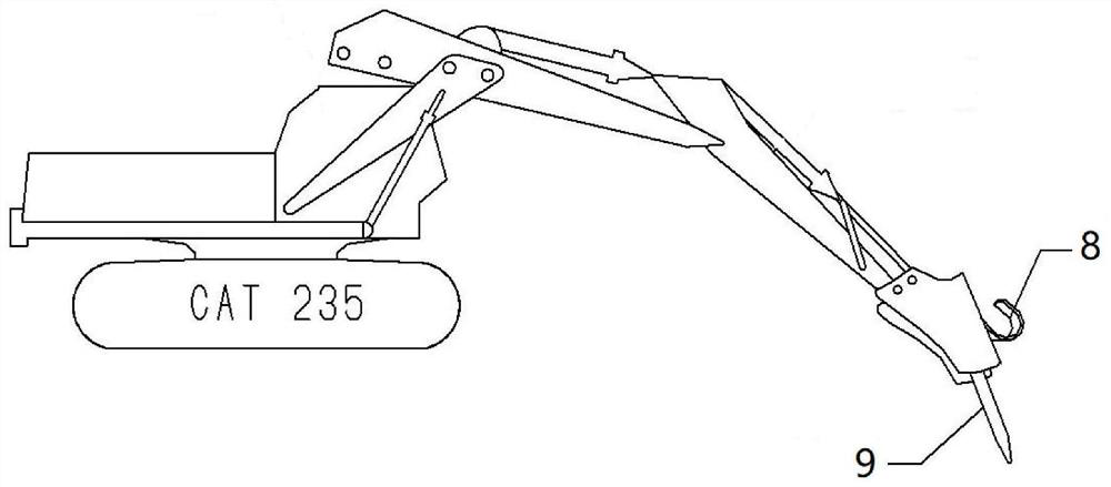
[0053] The invention utilizes the working platform built by the steel plate and the demolished building brick slag to reach any position of the building, so that the highest position of the building can also be dismantled; at the same time, a combination of long-arm excavator and ordinary excavator is adopted , which can ...


PUM

PropertyMeasurementUnit
Widthaaaaaaaaaa
Lengthaaaaaaaaaa
Diameteraaaaaaaaaa

Abstract

The invention provides a mechanical breaking demolition method for a low-rise building. The problem that a platform is difficult to build in an existing mechanical breaking demolition of a building issolved. The mechanical breaking demolition method comprises the following steps that S1, a warning area is delimited; S2, a predetermined collapse direction of the building is determined according tothe surrounding environment, non-bearing structures of the building are dismantled from top to bottom, dismantled brick slag is collected and flattened, and a steel plate is laid on the brick slag toform a working platform; S3, a dismantling machine runs to the corresponding working platform to continue to dismantle the non-bearing structure of the building until all the non-bearing structures are dismantled completely; S4, the multiple dismantling machines are adopted to dismantle bearing columns of the building from the lowest layer within a safety range according to the set collapse direction of the building, so that the building slowly collapses; and S5, after the building collapses, floor slabs, stand columns and beams of the building are dismantled layer by layer from top to bottomthrough the dismantling machines, and steel bars are cut and recycled till the whole building is dismantled completely.

Description

technical field [0001] The invention relates to a demolition construction method for low-rise buildings, in particular to a mechanized crushing and demolition method for low-rise buildings. Background technique [0002] With the increase of urban population, urban land resources are becoming more and more scarce, so there are more and more renovations of old communities. Some buildings that are old and inconsistent with the new urban planning need to be demolished, and the proportion of houses below 10 floors in these buildings is very high. [0003] At present, building demolition mainly includes mechanized crushing demolition, blasting demolition and manual chiseling. The blasting demolition method has a great impact on the surrounding area, and the dust generated pollutes the environment. Therefore, blasting is generally not used in the demolition of old low-rise buildings in cities. The demolition of houses by manual chiseling is not only inefficient, high in cost, but...

Claims


Application Information

Patent Timeline
IPC IPC(8): E04G23/08E01H3/02E02F5/30
CPCE01H3/02E02F5/30E04G23/082
Inventor 李功义李小红李武赵东华杨伟何海兵屈若枫
Owner CHINA RAILWAY 11TH BUREAU GRP
Why Eureka
Try Eureka