Movable drilling device for ground construction

A drilling device and mobile technology, applied in the direction of drilling equipment and methods, drilling tools, drilling equipment, etc., can solve the problems of unusable, time-consuming and laborious, difficult to operate smoothly and achieve a stable and fixed effect

Inactive Publication Date: 2021-03-02
陶寿松
View PDF0 Cites 2 Cited by
  • Summary
  • Abstract
  • Description
  • Claims
  • Application Information

AI Technical Summary

Problems solved by technology

[0003] However, the existing drilling work for ground construction is to drill holes on the ground through manual hand-held drilling machines, which is difficult to ensure smooth operation during drilling. Selecting a point to continue drilling is time-consuming and laborious

Method used


Image

  • Movable drilling device for ground construction
  • Movable drilling device for ground construction
  • Movable drilling device for ground construction

Examples


Embodiment 1

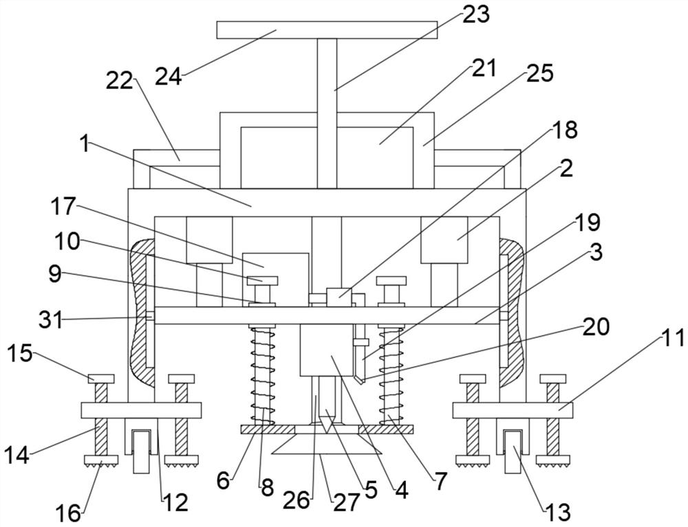
[0024] combine Figure 1-4 , a mobile drilling device for ground construction, comprising a 匚-shaped mounting frame 1, an electric push rod 2 is installed on the inner top of the 匚-shaped mounting frame 1, and a moving plate 3 is mounted on the movable end of the electric push rod 2 , the two sides of the moving plate 3 are slidably matched with the inner wall of the 匚-shaped mounting frame 1, the lower end of the moving plate 3 is equipped with a motor 4, the output end of the motor 4 is equipped with a drill bit 5, and the moving plate 3 slides Four moving rods 7 are connected, the upper ends of the four moving rods 7 are fixed with stoppers 10, the lower ends of the four moving rods 7 are connected with support plates 6, and the support plates 6 are provided with through holes, so The drill bit 5 is arranged above the through hole, a spring 8 sleeved on the outside of the moving rod 7 is fixed between the moving plate 3 and the support plate 6, and a water application mecha...

Embodiment 2

[0035] combine Figure 1-2 , a mobile drilling device for ground construction. This embodiment further defines the present invention on the basis of Embodiment 1.

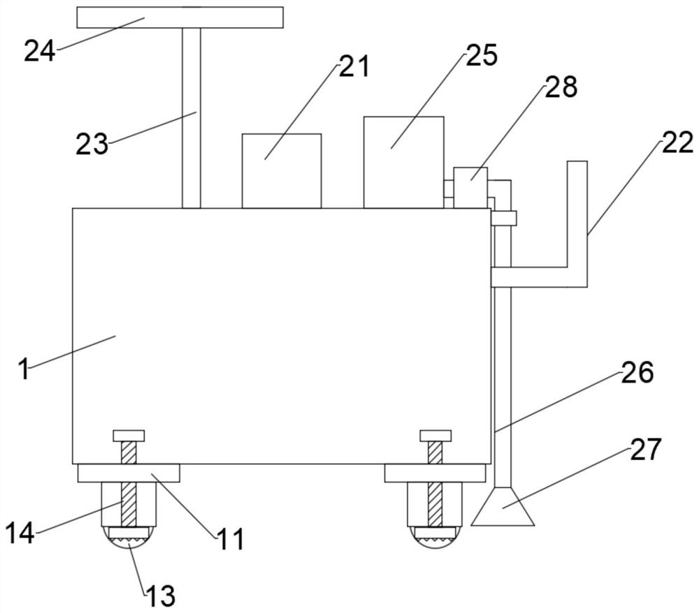
[0036] The slag removal mechanism includes a slag suction device 28, a slag suction cover 27, a slag suction pipe 26 and a collection box 25. The slag suction device 28 is installed on the upper end of the Yi-shaped mounting frame 1, and the front end of the slag suction device 28 passes through the The second connecting pipe is connected to the collection box 25, and the rear end of the slag absorber 28 is connected to the slag suction cover 27 through the slag suction pipe 26, and the slag suction pipe 26 is fixed on the rear side of the slag-shaped mounting frame 1 through a pipe clamp .

[0037] Specifically, through the slag suction device 28 in the slag cleaning mechanism, the waste slag at the back hole and around the hole will enter the collection box 25 through the slag suction cover 27, the slag suction ...


PUM


Abstract

The invention discloses a movable drilling device for ground construction. The movable drilling device comprises a left square bracket-shaped mounting frame, wherein electric push rods are mounted atthe inner top of the left square bracket-shaped mounting frame, a movable plate is mounted at the movable ends of the electric push rods, two sides of the movable plate are in sliding fit with the inner wall of the left square bracket-shaped mounting frame, a motor is mounted at the lower end of the movable plate, a drill bit is installed at the output end of the motor, four moving rods are slidably connected to the moving plate, stop blocks are fixed to the upper ends of the four moving rods, a supporting plate is connected to the lower ends of the four moving rods, a through hole is formed in the supporting plate, the drill bit is arranged above the through hole, and springs connected to the outer sides of the moving rods in a sleeving mode are fixed between the moving plate and the supporting plate. According to the movable drilling device, the whole device is stably supported through the supporting plate and the springs between the supporting plate and the moving plate, the drill bit can vertically drill into the ground conveniently, and therefore inconvenience caused by manual drilling is avoided.

Description

technical field [0001] The invention relates to the technical field of drilling equipment, in particular to a mobile drilling device for ground construction. Background technique [0002] In the construction of some infrastructure, it is necessary to drill holes in the ground and then install some basic settings. For example, the construction of community activity sites requires the installation of some fitness equipment, etc. The installation of traffic lights and street lights on the road requires the use of ground drilling. hole device. [0003] However, the existing drilling work for ground construction is to drill holes on the ground through manual hand-held drilling machines, which is difficult to ensure smooth operation during drilling. Selecting a point to continue drilling is time-consuming and laborious. Therefore, a kind of drilling device for mobile ground construction is proposed to solve the above problems. Contents of the invention [0004] The object of ...

Claims


Application Information

Patent Timeline
Patent Type & Authority Applications(China)
IPC IPC(8): E21B7/02E21B12/06E21B12/00
CPCE21B7/02E21B12/00E21B12/06
Inventor 陶寿松
Owner 陶寿松
Why Eureka
Try Eureka