Efficient punching equipment for power panel machining and punching method for power panel machining

A power panel and punching technology, applied in metal processing and other directions, can solve problems such as increased production cost, low efficiency, and easy fatigue, and achieve the effects of improving the quality of finished products, improving stability, and improving flexibility

Pending Publication Date: 2022-01-28
惠州市立华五金电子有限公司
View PDF7 Cites 0 Cited by
  • Summary
  • Abstract
  • Description
  • Claims
  • Application Information

AI Technical Summary

Problems solved by technology

[0003] When the existing power panel is processed, it needs to be punched, and the existing punching equipment is mostly directly operated manually, and after a long time of operation, the manual is prone to fatigue, which leads to the punching process. Mistakes will affect the quality of the product, cause damage to the product, or even scrap it, resulting in waste of materials, resulting in increased production costs, and manual operation can only be done one by one for drilling, which is very inefficient

Method used


Image

  • Efficient punching equipment for power panel machining and punching method for power panel machining
  • Efficient punching equipment for power panel machining and punching method for power panel machining
  • Efficient punching equipment for power panel machining and punching method for power panel machining

Examples


Embodiment Construction

[0031] The following will clearly and completely describe the technical solutions in the embodiments of the present invention with reference to the accompanying drawings in the embodiments of the present invention. Obviously, the described embodiments are only some, not all, embodiments of the present invention. Based on the embodiments of the present invention, all other embodiments obtained by persons of ordinary skill in the art without making creative efforts belong to the protection scope of the present invention.

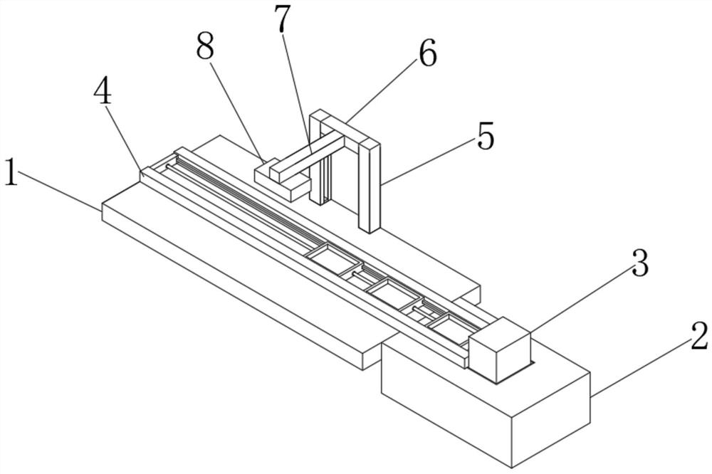
[0032] The present invention provides such Figure 1-6 The shown high-efficiency punching equipment for power panel processing includes a console 1 and a base 2, the console 1 is fixedly connected to one side of the base 2, the top of the base 2 is fixedly connected to a motor casing 3, and the top of the console 1 Equipped with a drilling mechanism;

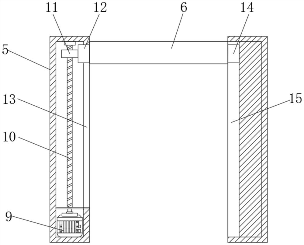
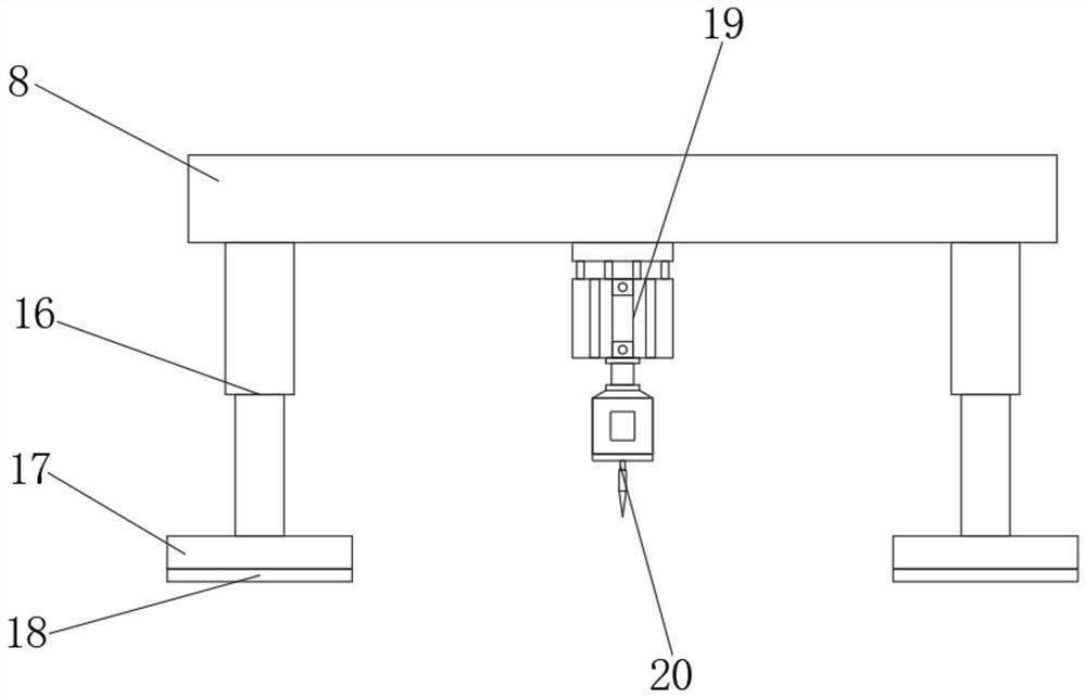
[0033] The drilling mechanism includes a column 5, a cross bar 6, a support bar 7 and a drilling plate 8. Th...


PUM


Abstract

The invention discloses efficient punching equipment for power panel machining and a punching method for power panel machining. The efficient punching equipment comprises an operation table and a base; the operation table is fixedly connected to one side of the base; a motor shell is fixedly connected to the top end of the base; a drilling mechanism is arranged at the top end of the operation table; the drilling mechanism comprises stand columns, a transverse rod, a supporting rod and a drilling plate; the two stand columns are fixedly connected to the two sides of the top end of the operation table respectively; the transverse rod is arranged between the two stand columns; the supporting rod is fixedly connected to the outer side of the transverse rod; and the drilling plate is fixedly connected to the bottom end of the supporting rod. According to the efficient punching equipment for power panel machining and the punching method for power panel machining, a first motor, a first threaded rod, a first threaded sleeve, a first sliding block and the transverse rod are adopted, the other side of the transverse rod is fixedly connected with a second sliding block, and the second sliding block is slidably connected to the inner side of a second sliding groove; and through the above arrangement, the transverse rod is effectively driven to move up and down, that is, the drilling plate is driven to move up and down, and thus, the flexibility of the equipment is improved, and manual operation is reduced.

Description

technical field [0001] The invention relates to the field of power panel punching, in particular to a high-efficiency punching device for power panel processing and a punching method thereof. Background technique [0002] In electronic products, the power supply is one of the essential equipment. In small electronic products, the power supply is often composed of a set of power supply circuits. The power supply is made into a power panel through a PCB board. Switches, power sockets, various weak current sockets, etc.) are fixed on the electronic products with a shell to provide working power for the electronic products. [0003] When the existing power panel is being processed, it needs to be punched, and the existing punching equipment is mostly manually operated directly, and after a long time of operation, the manual is prone to fatigue, resulting in Mistakes will affect the quality of the product, cause damage to the product, or even be scrapped, resulting in waste of m...

Claims


Application Information

Patent Timeline
Patent Type & Authority Applications(China)
IPC IPC(8): B26F1/16B26D5/06B26D5/08B26D7/02B26D7/20
CPCB26F1/16B26D5/06B26D5/086B26D7/025B26D7/20B26F2210/08
Inventor 谢立飞肖笔秋
Owner 惠州市立华五金电子有限公司
Why Eureka
Try Eureka