Rapid drying device for LED shell machining material

A technology for LED housing and processing materials, which is applied in drying, drying machine, drying solid materials, etc., can solve the problems of reducing drying efficiency, inconvenient fixing of LED housing, and large difference in center temperature.

Inactive Publication Date: 2021-03-02
SUZHOU XUNNENG OPTOELECTRONICS TECH CO LTD
View PDF13 Cites 0 Cited by
  • Summary
  • Abstract
  • Description
  • Claims
  • Application Information

AI Technical Summary

Problems solved by technology

Most of the existing drying devices are conveyor belt-type drying structures. Through the translational transportation of the LED housing on the conveyor belt, the drying structure is used to dry the conveyor belt. However, in actual operation, the LED shell is often The shell stays in the equipment for insufficient time, and the

Method used


Image

  • Rapid drying device for LED shell machining material
  • Rapid drying device for LED shell machining material
  • Rapid drying device for LED shell machining material

Examples


Embodiment 1

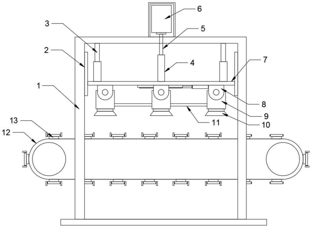
[0022]SeeFigure 1~4In the embodiment of the present invention, a rapid drying device for LED housing processing materials includes a fixing frame 1, a conveyor belt 12, and a fan 22. The fixing frame 1 is provided with slide rails 2 on the left and right sides at the upper end of the inner side. The inner side is provided with a support frame 7. The upper end of the support frame 7 is equipped with telescopic rods 3 on the left and right sides. The top of the telescopic rod 3 is connected to the top of the inner side of the fixing frame 1. The cross-sectional shape of the slide rail 2 is concave. The slide rail 2 and the support frame 7 are at the left and right ends Concave-convex connection, two telescopic rods 3 are arranged between the upper end of the support frame 7 and the inner side of the fixed frame 1; the middle of the top of the support frame 7 is installed with a fixed cylinder 4, the middle of the top of the fixed frame 1 is installed with a rotating electric machine 6...

Embodiment 2

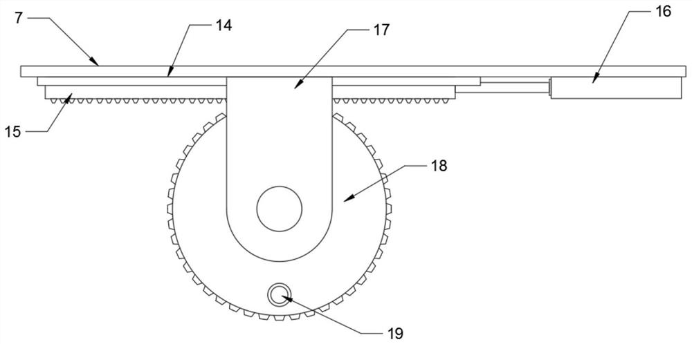
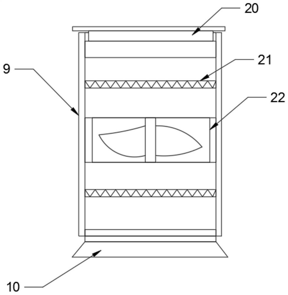
[0026]SeeFigure 5 In the embodiment of the present invention, a rapid drying device for LED housing processing materials includes a fixing frame 1, a conveyor belt 12, and a fan 22. The fixing frame 1 is provided with slide rails 2 on the left and right sides at the upper end of the inner side. The inner side is provided with a support frame 7, the upper and left sides of the support frame 7 are equipped with telescopic rods 3, the top of the telescopic rod 3 is connected to the top of the inner side of the fixed frame 1, the middle of the top of the support frame 7 is installed with a fixed cylinder 4, and the middle of the top of the fixed frame 1 is installed with a rotation The motor 6 and the rotating motor 6 are equipped with a threaded rod 5 at the front end of the shaft, and the inner side of the fixed cylinder 4 is connected with a threaded rod 5; a first turret 8 is installed in the middle of the bottom end of the support frame 7, and a cylinder 9 is installed on the inner...

Embodiment 3

[0028]In the embodiment of the present invention, a rapid drying device for LED housing processing materials includes a fixing frame 1, a conveyor belt 12, and a fan 22. The fixing frame 1 is provided with slide rails 2 on the left and right sides at the upper end of the inner side, and the inner side of the slide rail 2 There is a support frame 7. The upper and left sides of the support frame 7 are equipped with telescopic rods 3, the top of the telescopic rod 3 is connected to the top of the inner side of the fixing frame 1, the middle of the top of the support frame 7 is installed with a fixed cylinder 4, and the middle of the top of the fixing frame 1 is installed with a rotating motor 6. The front end of the rotating motor 6 is equipped with a threaded rod 5, and the inner side of the fixed cylinder 4 is connected with a threaded rod 5; the inner bottom of the fixing frame 1 is provided with a conveyor belt 12, the surface of the conveyor belt 12 is installed with a fixing seat...


PUM


Abstract

The invention discloses a rapid drying device for an LED shell machining material. The rapid drying device comprises a fixing frame, a conveying belt and fans, wherein sliding rails are arranged on the left side and the right side of the upper end of the inner side of the fixing frame, a supporting frame is arranged on the inner sides of the sliding rails, a fixing barrel is installed in the middle of the top end of the supporting frame, a rotating motor is installed in the middle of the top end of the fixing frame, and a threaded rod is installed at the front end of a rotating shaft of the rotating motor; first rotating frames are mounted in the middle of the bottom end of the supporting frame, a cylinder is installed on the inner side of each first rotating frame, a filter screen is installed at the top end of the inner side of each cylinder, a fan is installed in the middle of the inner side of each cylinder, heating wires are installed at the upper end and the lower end of each fan, and an air outlet is formed in the bottom end of each cylinder; and a guide rail and a rack are installed on the rear side of the bottom end of the supporting frame, a telescopic motor is arranged at the right end of the rack, second rotating frames and gears are installed on the outer side of the guide rail, rolling bearings are installed on the outer edges of the gears, and connecting rods aremounted on outer sides of the rolling bearings. The rapid drying device is reasonable in structure, LED shells can be conveniently fixed and dried, so that the drying is uniform, then the drying efficiency is effectively improved, and the drying effect is good.

Description

Technical field[0001]The invention relates to the technical field of LED housing processing, in particular to a rapid drying device for LED housing processing materials.Background technique[0002]Light-emitting diodes are referred to as LEDs for short. It is a type of semiconductor diode that can convert electrical energy into light energy. Like ordinary diodes, light-emitting diodes are composed of a PN junction, and they also have unidirectional conductivity. The energy states of electrons and holes in different semiconductor materials are different. When electrons and holes recombine, the energy released is somewhat different. The more energy released, the shorter the wavelength of the emitted light. Most of the existing drying devices are conveyor belt drying structures. The LED shells on the conveyor belt are translated and conveyed, and the conveyor belt is equipped with a drying structure for drying. However, in actual operation, LEDs are often used for drying. The shell stays...

Claims


Application Information

Patent Timeline
IPC IPC(8): F26B15/18F26B21/00F26B25/00F26B25/02
CPCF26B15/18F26B21/001F26B21/004F26B25/00F26B25/02
Inventor 周福珍
Owner SUZHOU XUNNENG OPTOELECTRONICS TECH CO LTD
Why Eureka
Try Eureka