Experimental device taking direct-current vibration motor as vibration wave source and experimental method thereof
A technology of vibration motor and vibration wave source, which is applied in the field of physical experiments, can solve problems such as loosening of vibration strings, loose connection of vibration strings, and affecting experiments, etc., to achieve the effects of increasing friction, preventing severe wear, and reducing friction
- Summary
- Abstract
- Description
- Claims
- Application Information
AI Technical Summary
Problems solved by technology
Method used
Image
Examples
Embodiment 1
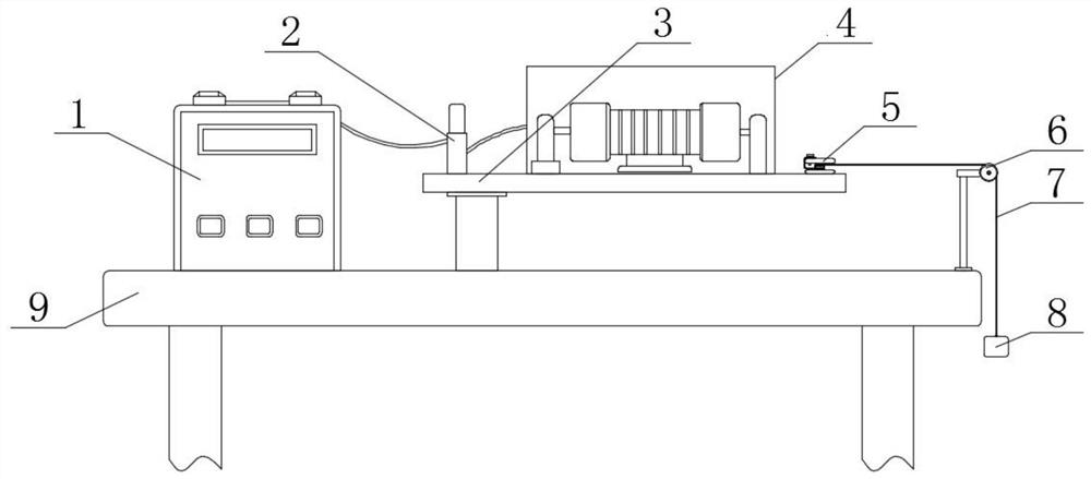
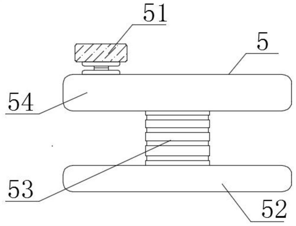
[0022] Such as Figure 1-2 As shown, an experimental device using a DC vibrating motor as a vibration wave source includes a test bench 9, a DC power supply velocimeter 1 is arranged on the left side of the upper end of the test bench 9, and the lower right of the DC power supply velocimeter 1 is located at the upper end of the test bench 9 The left middle part is fixed with a column, and the upper end of the column is fixed with a fixed plate 3, and the upper middle of the fixed plate 3 is fixed with a vibration motor part 4. The vibration motor part 4 is mainly composed of a vibration motor, a fixed frame, a speed measuring disc and a photoelectric gate. At the left position of component 4, there is a terminal 2 connected by wires, and the terminal 2 is fixed on the fixed plate 3 and connected with the DC power supply speedometer 1 by wires, and the upper right side of the test bench 9 is fixed with a guide wheel mechanism 6. The upper right end of the guide wheel mechanism ...
Embodiment 2
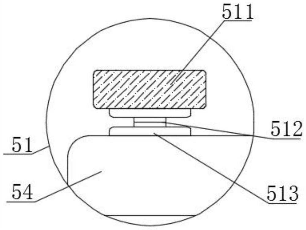
[0025] Such as image 3 As shown, an experimental device using a DC vibration motor as a vibration wave source, the fixed knob 51 includes a knob head 511, a screw rod 512 and a rubber pad 513, the lower end of the knob head 511 is fixed with a rubber pad 513, and the upper side of the rubber pad 513 is located at the upper limit. The upper end of the plate 54 is sleeved with a screw rod 512 .
[0026] When in use, the extension part of the vibrating string 7 wound on the winding post 53 is wound on the screw rod 512, and is located between the two rubber pads 513. Grab the knob head 511 and force it to drive the screw rod 512 and the upper limit plate 54 to spiral. Rotate to fix the vibrating string 7, and the concave-convex pattern on the surface of the knob head 511 increases the friction force. During the rotation process, the vibrating string 7 is protected by two rubber pads 513 to reduce the friction force and prevent the vibrating string 7 from being severely worn. Pr...
PUM
 Abstract
Description
Claims
Application Information
 - R&D
- Intellectual Property
- Life Sciences
- Materials
- Tech Scout
- Unparalleled Data Quality
- Higher Quality Content
- 60% Fewer Hallucinations
Browse by: Latest US Patents, China's latest patents, Technical Efficacy Thesaurus, Application Domain, Technology Topic, Popular Technical Reports.
© 2025 PatSnap. All rights reserved.Legal|Privacy policy|Modern Slavery Act Transparency Statement|Sitemap|About US| Contact US: help@patsnap.com


