

Rechargeable device, charger and charging system
A technology for charging equipment and chargers, applied in charging/discharging current/voltage regulation, current collectors, battery circuit devices, etc., which can solve problems such as long boosting time and cumbersome software processes
- Summary
- Abstract
- Description
- Claims
- Application Information
AI Technical Summary
Problems solved by technology
Method used
Image

Examples
Embodiment 1
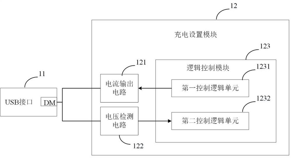
[0076] figure 1 A chargeable device of this embodiment is shown, which includes: a USB interface 11 and a charging setting module 12 . USB interface 11 is a 4pin USB interface, including VBUS (power line) pin, DM (data +) pin, DP (data -) pin and GND (ground) pin. Wherein, the VBUS pin is connected to the charging module in the rechargeable device, and the charging module includes relevant circuits required for charging the existing device, such as a voltage converter, a rechargeable battery, and the like. The DP pin is shorted. The GND pin is grounded. The DM pin is connected with the charging setting module 12 . The charging setting module 12 sends the first signal and receives the second signal through the DM pin to realize the interaction with the charger. The first signal may be a current signal for controlling the charger. The second signal may be a voltage signal, which is used to feed back whether the first signal is responsive to the control of the charger. Sinc...
Embodiment 2
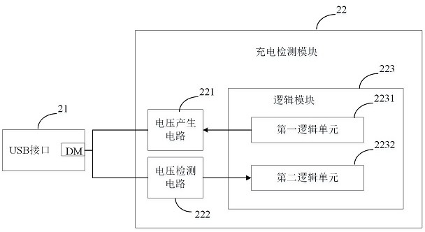
[0109] image 3 A charger of this embodiment is shown. It includes: a USB interface 21 and a charging detection module 22 . The USB interface 21 is a 4pin USB interface, including a VBUS pin, a DM pin, a DP pin and a GND pin. Among them, the VBUS pin is connected to the adapter or power plug in the charger, or related circuits required for charging other devices. The DP pin is shorted. The GND pin is grounded. The DM pin is connected with the charging detection module 22 . The charging detection module 22 receives the first signal and sends the second signal through the DM pin to realize the interaction with the rechargeable device. The first signal may be a current signal for controlling the charger. The second signal may be a voltage signal, which is used to feed back whether the first signal is responsive to the control of the charger. Since the first signal and the second signal are both analog signals, the generation and detection of the first signal and the second...
Embodiment 3
[0130] A charging system includes a compatible rechargeable device and a charger. The USB interface of the rechargeable device and the USB interface of the charger are connected through a USB cable, and the analog signal interaction is performed through the DM pins of the respective USB interfaces.
[0131] The rechargeable device adopts the structure of embodiment 1, and the charger adopts the structure of embodiment 2. It should be noted that the compatible rechargeable device and the charger have the same corresponding table in advance, which can analyze the current value and voltage value on the DM pin, have the same number of comparators, and the threshold voltage of the comparators is the same .
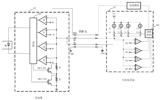
[0132] Combine below figure 2 The process of interaction between the rechargeable device and the charger in this embodiment is described in detail:
[0133]In the figure, the rechargeable device has 4 current sources I1, I2, I3, I4, corresponding switches S1, S2, S3, S4 and...
PUM
 Abstract
Description
Claims
Application Information