Metal cutting tool for high-speed cutting

A metal cutting and high-speed cutting technology, applied in metal processing equipment, metal processing mechanical parts, manufacturing tools, etc., can solve the problems of easy deformation and damage, poor stability, etc., to improve stability, reduce temperature uniformly, and simplify installation methods. Effect

Inactive Publication Date: 2021-03-05
江苏海博工具产业研究院有限公司
View PDF0 Cites 6 Cited by
  • Summary
  • Abstract
  • Description
  • Claims
  • Application Information

AI Technical Summary

Problems solved by technology

[0004] The purpose of the present invention is to solve the shortcomings of poor stability and easy deformation and damage in the prior art, and propose a metal cutting tool for high-speed cutting

Method used


Image

  • Metal cutting tool for high-speed cutting
  • Metal cutting tool for high-speed cutting
  • Metal cutting tool for high-speed cutting

Examples


Embodiment Construction

[0020] The following will clearly and completely describe the technical solutions in the embodiments of the present invention with reference to the accompanying drawings in the embodiments of the present invention. Obviously, the described embodiments are only some, not all, embodiments of the present invention.

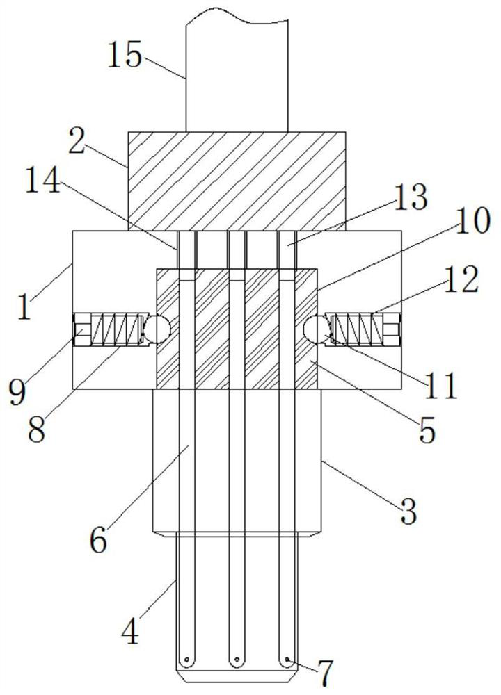
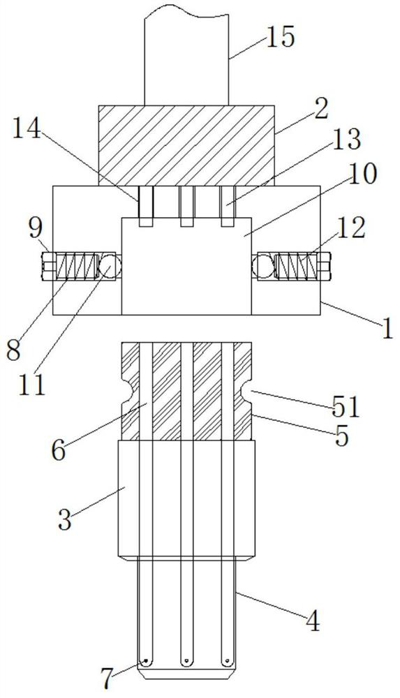
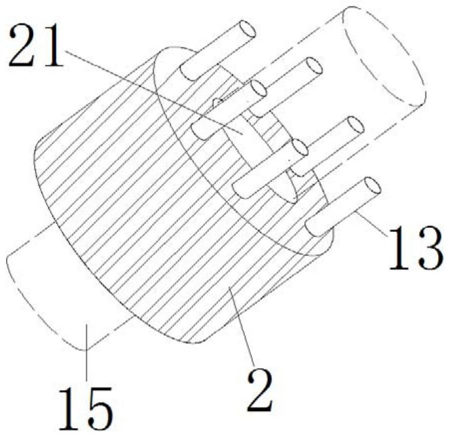
[0021] refer to Figure 1-4 , a metal cutting tool for high-speed cutting, including a mounting base 1, a handle 3 and a cutter head 4, the top of the mounting base 1 is respectively fixed with a cooling box 2 and a drive spindle 15 by bolts, and the bottom of the cooling box 2 The liquid spray pipeline 13 is fixedly connected with the flange plate, and the installation seat 1 is provided with an installation groove 10, and the inner wall of the installation groove 10 is respectively provided with a screw hole 8 and a through hole 14, and the screw hole 8 and the through hole 14 are connected with the installation groove 10. The inside is connected, the inside of the...


PUM


Abstract

The invention relates to the technical field of metal cutting tools, in particular to a metal cutting tool for high-speed cutting, and overcomes the defects of poor stability and easiness in deformation and damage in the prior art. The metal cutting tool comprises a mounting seat, a tool handle and a tool bit; a cooling box and a driving spindle are fixed to the top of the mounting seat through bolts; a liquid spraying pipeline is fixedly connected to the bottom of the cooling box through a flange plate; a mounting groove is formed in the mounting seat; screw holes and through holes are formedin the inner wall of the mounting groove; the screw holes and the through holes communicate with the interior of the mounting groove; and positioning steel balls are embedded into the screw holes. Through arrangement of the structures such as locking screws, damping springs, positioning steel balls, mounting blocks and hemispherical grooves, the mounting mode of the tool is simplified, the damping springs in the tool can play a role in damping the tool after being mounted, the overall stability of the tool is improved, and the machining precision of the tool is ensured.

Description

technical field [0001] The invention relates to the technical field of metal cutting tools, in particular to a metal cutting tool for high-speed cutting. Background technique [0002] Shank knives usually have three types: rectangular shank, cylindrical shank and conical shank. Turning tools, planing tools, etc. are generally rectangular shanks; conical shanks bear axial thrust by taper, and transmit torque with the help of friction; cylindrical shanks are generally suitable for smaller twist drills, end mills and other tools. The resulting frictional force transmits the torque. The shank of many shank knives is made of low alloy steel, and the working part is made of high speed steel butt welding the two parts. [0003] At present, the metal cutting tools on the market have too much vibration force during high-speed cutting, and the overall stability of the tool is low, which makes it difficult for the tool to guarantee high-precision machining of the product, and the too...

Claims


Application Information

Patent Timeline
Patent Type & Authority Applications(China)
IPC IPC(8): B23Q11/10B23Q11/00
CPCB23Q11/0032B23Q11/10
Inventor 陈明马海善
Owner 江苏海博工具产业研究院有限公司
Why Eureka
Try Eureka