Auxiliary device for replacing impeller bearing of wind turbine

An auxiliary device and wind motor technology, applied in the direction of workbench, manufacturing tools, etc., can solve problems such as unstable center of gravity, frequent accidents, etc., and achieve the effect of avoiding rotation

Inactive Publication Date: 2021-03-05
李军
View PDF1 Cites 1 Cited by
  • Summary
  • Abstract
  • Description
  • Claims
  • Application Information

AI Technical Summary

Problems solved by technology

[0004] In order to overcome the problem in the prior art that frequent accidents occur due to the unstable center of gravity caused by the swing of the impeller when lifting a huge impeller, the present invention provides an auxiliary device for replacing the bearing of the wind turbine impeller

Method used


Image

  • Auxiliary device for replacing impeller bearing of wind turbine
  • Auxiliary device for replacing impeller bearing of wind turbine
  • Auxiliary device for replacing impeller bearing of wind turbine

Examples


Embodiment 1

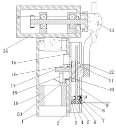
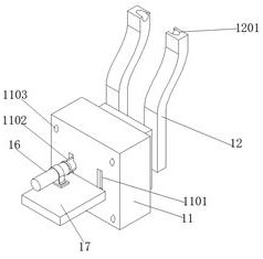
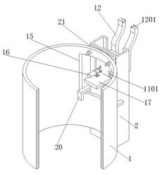
[0029] refer to Figure 1-5 , the wind turbine impeller bearing replacement auxiliary device, including the inner support tube 19 fixed on the inner wall of the support tower tube 1, and the chassis shell 14 that is rotatably connected to the top of the inner support tube 19, the middle of the chassis shell 14 is connected with a transmission shaft, and the transmission The end of the shaft is sleeved with an impeller head 13, a C-shaped steel column 2, and a T-shaped slider 11 is slidably connected in the chute of the C-shaped steel column 2. There is a window 15, and two parallel rectangular sockets 1101 are opened on the side of the T-shaped slider 11 far away from the bottom of the groove, and the two sockets 1101 are inserted with a board 1204, and the two boards 1204 are far away from the support tower One end of the pipe 1 is fixed with a U-shaped support rod 12, and a single support rod of the U-shaped support rod 12 is arranged in a Z-shaped structure, and the top of ...

Embodiment 2

[0039] refer to figure 1 and Figure 5 , wind turbine impeller bearing replacement auxiliary device, compared with embodiment 1, this embodiment also includes an annular groove on the upper surface of the turntable 4 near the peripheral edge, and a non-return tooth 703 is arranged in the annular groove, and the fixed plate 5 There is a mounting hole on the upper surface of the mounting hole, and an opening downward positioning barrel 7 is clamped in the mounting hole. The bottom opening of the positioning barrel 7 is slidably connected with an inner sliding rod 702, and the bottom end of the inner sliding rod 702 is provided with a triangular anti-skid Back-moving spring 701 is fixed between the top of the inner slide bar 702 and the bottom of the barrel.

[0040] Wherein, the top of the inner sliding rod 702 is fixed with a pull rod, and the top of the pull rod is fixed with a pull ring, so that it can be locked at any time when the transmission screw 9 rotates during use, s...


PUM


Abstract

The invention belongs to the technical field of wind power equipment, and particularly relates to an auxiliary device for replacing an impeller bearing of a wind turbine. The auxiliary device aims atsolving the problem that accidents frequently occur due to the fact that the gravity center is unstable due to the swing of an impeller when the huge impeller is lifted in the prior art. According tothe scheme, the auxiliary device comprises an inner supporting pipe fixed on the inner wall of a supporting tower pipe and a case shell rotationally connected to the top end of the inner supporting pipe, wherein a transmission shaft is rotationally connected to the middle of the case shell. According to the auxiliary device, when the head of the impeller needs to be disassembled in the using process, a U-shaped supporting rod is horizontally moved to support the roots of two impellers on the outer wall of the head of the impeller, then the head of the impeller can be slowly suspended and fixedat the original position by operating a manual hydraulic ejector rod, then the radial bearing force of a transmission rod can be disassembled, and at the moment, the bearing can be replaced.

Description

technical field [0001] The invention relates to the technical field of wind power equipment, in particular to an auxiliary device for replacing bearings of wind turbine impellers. Background technique [0002] At present, with the increasing demand for energy, offshore wind power generation has attracted more and more attention. However, the wind turbines are bulky and heavy, and transportation and hoisting are very difficult. The wind power installation ship realizes the transportation and installation of wind turbines. For hoisting, the wind power installation ship has 4 to 6 legs that can be lifted vertically. The legs inserted into the seabed are used to lift the hull off the sea surface to become a workbench, and the wind turbines are installed by means of a crane on the deck. [0003] After retrieval, the patent document with the authorized announcement number CN201273342 discloses assembly equipment for wind power bearings. The wind power bearings have mounting holes ...

Claims


Application Information

Patent Timeline
Patent Type & Authority Applications(China)
IPC IPC(8): B25H1/00
CPCB25H1/00
Inventor 李军
Owner 李军
Why Eureka
Try Eureka