Rail train, vehicle-mounted controller and speed measurement method and device of rail train

A rail train and speed measurement technology, applied in the field of rail trains, can solve the problems of inaccurate speed measurement and low speed measurement accuracy, and achieve the effect of accurate measurement results and accurate train speed

Active Publication Date: 2021-03-05
BYD CO LTD
View PDF24 Cites 3 Cited by
  • Summary
  • Abstract
  • Description
  • Claims
  • Application Information

AI Technical Summary

Problems solved by technology

[0005] The embodiments of the present application provide a rail train, an on-board controller, and a speed measurement method and device for a rail train, so as to solve the technical problems of low accuracy and inaccurate speed measurement of rail trains in the prior art

Method used


Image

  • Rail train, vehicle-mounted controller and speed measurement method and device of rail train
  • Rail train, vehicle-mounted controller and speed measurement method and device of rail train
  • Rail train, vehicle-mounted controller and speed measurement method and device of rail train

Examples


Embodiment Construction

[0027] In order to make the purpose, technical solution and advantages of the present application clearer, the present application will be further described in detail below in conjunction with the accompanying drawings and embodiments. It should be understood that the specific embodiments described here are only used to explain the present application, and are not intended to limit the present application.

[0028] The implementation of the present application is described in detail below in conjunction with specific drawings:

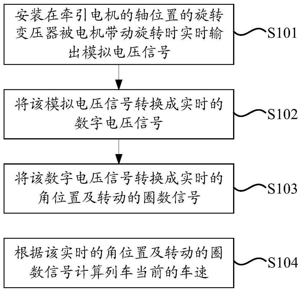
[0029] figure 2 It is a schematic flow chart of the speed measuring method of rail train in an embodiment of the present application, combined below figure 2 Describe in detail the method for measuring the speed of rail trains according to an embodiment of the present application, such as figure 2 As shown, the speed measuring method of the rail train comprises the following steps S101 to S104:

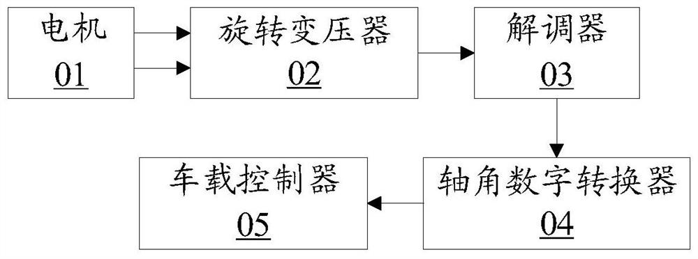
[0030] S101. The resolver installed on the axis of...


PUM


Abstract

The invention discloses a rail train, a vehicle-mounted controller and a speed measurement method and device of the rail train, which are applied to the field of rail trains and used for improving theprecision and accuracy of train speed measurement. The speed measurement method of the rail train comprises the steps of when a rotary transformer installed at the shaft position of a traction motoris driven by the motor to rotate, outputting an analog voltage signal in real time; converting the analog voltage signal into a real-time digital voltage signal; converting the digital voltage signalinto a real-time angular position and a rotation turn number signal; and calculating the current speed of the train according to the real-time angular position and the rotation turn number signal.

Description

technical field [0001] The present application relates to the technical field of rail trains, in particular to a rail train, an on-board controller, and a speed measuring method and device for a rail train. Background technique [0002] Monorails currently use compact, low-maintenance photoelectric speed sensors. The speed sensor is equipped with a grating, a luminous tube and a receiving tube. It scans the grating disc synchronized with the wheel shaft. After the receiving tube receives the light and senses the change of light and dark, the sensor can output a square wave signal that is linearly proportional to the speed. Wave signal calculation can obtain the rotational speed of the measured object. [0003] On the one hand, because the photoelectric speed sensor is limited by the volume of the photocell, it has a large volume and requires high installation accuracy. Due to the size of the grating disc, the number of gratings in the period is limited, resulting in low sen...

Claims


Application Information

Patent Timeline
Patent Type & Authority Applications(China)
IPC IPC(8): B61L25/02
CPCB61L25/021
Inventor 吕世超黄诚雄晏君
Owner BYD CO LTD
Why Eureka
Try Eureka