Prefabricated bathroom and kitchen floor, mounting structure, and construction method

A construction method and floor slab technology, applied in the direction of floor slabs, building components, building structures, etc., can solve the problems of long construction period, prolonged construction period, high construction noise, etc., so as to shorten the on-site construction period, accelerate the construction progress, and have high production efficiency. Effect

Pending Publication Date: 2021-03-05
E MAN CONSTR CO LTD
View PDF5 Cites 0 Cited by
  • Summary
  • Abstract
  • Description
  • Claims
  • Application Information

AI Technical Summary

Problems solved by technology

Please refer to figure 1 , since the strength of the concrete used in the bathroom kitchen floor 100 is different from that of the same cast-in-place structural exterior wall 101, they need to be poured separately, resulting in a joint between the bathroom kitchen floor 100 and the structural exterior wall 101, namely figure 1 In the middle II position, not only is this position prone to water seepage, but there are usually many steel bars at the corner of the II position, and the quality of on-site pouring is also difficult to guarantee
Please continue to refer figure 1 , the non-structural interior wall 102 of the bathroom or kitchen and the bath kitchen floor 100 also need to be poured separately, resulting in construction joints at the junction of the non-structural interior wall 102 and the bath kitchen floor 100, namely figure 1 In the I position, because the construction joints are easy to contact the ground water, long-term immersion in water is easy to seep into the steel bars in the bathroom and kitchen floors, thereby corroding or destroying the floor structure
In addition, the floor of the renovated bathroom or kitchen is flush with the construction joints at the root of the interior wall 102, which also makes it easy for the accumulated water on the ground to penetrate into the joints.
In addition, on-site construction is not easy to manage, the quality of pouring products is low, the construction period is long, the construction noise is large, and materials are wasted for later decoration, etc.
In addition, once the sunken bathroom and kitchen floor slab poured on site fails the waterproof test, various measures must be taken to remedy the concrete density. In severe cases, it may even require demolition and re-pouring, prolonging the construction period

Method used


Image

  • Prefabricated bathroom and kitchen floor, mounting structure, and construction method
  • Prefabricated bathroom and kitchen floor, mounting structure, and construction method
  • Prefabricated bathroom and kitchen floor, mounting structure, and construction method

Examples


Embodiment Construction

[0035] The present invention will be described in further detail below in conjunction with the accompanying drawings.

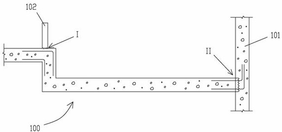
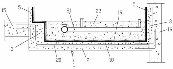
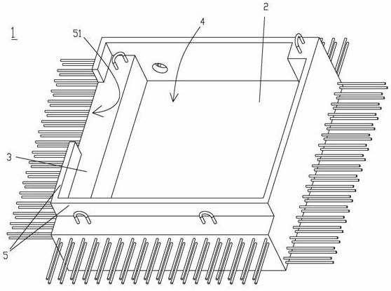
[0036] According to an object of the present invention, a prefabricated bathroom and kitchen floor is provided, figure 2 A cross-sectional view of the installation structure of the prefabricated bathroom and kitchen floor slab is schematically shown according to an embodiment of the present invention.

[0037] Please refer to figure 2, a prefabricated bathroom and kitchen floor. The prefabricated floor 1 as the main body of the prefabricated bathroom and kitchen floor is formed by one-time pouring of concrete. The prefabricated floor 1 includes a bottom slab 2 and a side wall 3 perpendicular to the bottom slab 1 and extending upward. The bottom slab 2 and the side wall 3 A groove 4 with an upward opening is formed, and the top surface of the side wall 3 is provided with a vertically upwardly extending low wall 5 formed by pouring. The inner walls of the gr...


PUM


Abstract

The invention discloses a construction method of a prefabricated bathroom and kitchen floor; the prefabricated bathroom and kitchen floor is integrally cast and formed in a factory; and the arrangement of a lamp throat pipe and a wayer drainage pipe, waterproof treatment, backfilling and the like are all carried out in the factory, so that the construction period is shortened, the field noise is reduced, the bathroom and kitchen waterproof performance is improved, and material waste is reduced. The invention further discloses the prefabricated bathroom and kitchen floor and a mounting structure thereof.

Description

technical field [0001] The invention relates to the field of construction, in particular to a prefabricated bathroom and kitchen floor, an installation structure and a construction method. Background technique [0002] Bathrooms and kitchens in modern buildings generally choose to be sunken. The sunken bathroom kitchen refers to the partial or overall sinking of the bathroom or kitchen to a height of 35-40cm from the corresponding floor during construction, and the horizontal drainage pipes of the bathroom and kitchen are arranged below. within the sunken area, and then backfill with lightweight material. The sewage pipe of the sunken bathroom kitchen does not need to pass through the floor of the same floor, and can realize drainage on the same floor. If there is a situation that needs to be cleaned and dredged, the problem can be solved in this floor. [0003] Existing sunken bathroom kitchen floor slabs are often equipped with molds at the bathroom kitchen position on th...

Claims


Application Information

Patent Timeline
Patent Type & Authority Applications(China)
IPC IPC(8): E04B5/48
CPCE04B5/48
Inventor 黃永灏
Owner E MAN CONSTR CO LTD
Why Eureka
Try Eureka