Floor heating bearing base plate structure

A base plate and floor heating technology, which is applied to local raised floors, building structures, floors, etc., can solve the problems of inconvenient screw operation, large base plate width, and difficulty in meeting quality requirements for flatness, so as to strengthen the tightness of the overall structure , reduce friction and shaking, good heat insulation effect

Pending Publication Date: 2021-03-05
ZHEJIANG YASHA DECORATION
View PDF1 Cites 2 Cited by
  • Summary
  • Abstract
  • Description
  • Claims
  • Application Information

AI Technical Summary

Problems solved by technology

[0004] For example, a floor heating substrate proposed in Chinese patent CN201920603445.7 has a large substrate width and high processing difficulty, and the flatness of the board itself is difficult to meet the quality requirements
The substrate needs to be opened, and the remaining material after cutting the substrate after the hole is cut cannot be used, and the utilization rate of the material is low; there is no combined clamping structure on the rib structure on both sides of the substrate, which cannot be stably matched with each other, and it is easy to cause two adjacent boards There is a large difference in the height difference between them, which affects the user experience. In addition, it is extremely inconvenient to operate when the actual screw is locked, and it is difficult to adjust this situation.
Furthermore, the problem of hole alignment needs to be considered during the deepening process, that is, when adjacent plates are misplaced, the hole positions need to be completely aligned. At this time, the typesetting is difficult and takes a long time

Method used


Image

  • Floor heating bearing base plate structure
  • Floor heating bearing base plate structure
  • Floor heating bearing base plate structure

Examples


Embodiment Construction

[0031] In order to make the purpose, technical solutions and advantages of the embodiments of the present invention clearer, the technical solutions in the embodiments of the present invention will be clearly and completely described below in conjunction with the drawings in the embodiments of the present invention. Obviously, the described embodiments It is a part of embodiments of the present invention, but not all embodiments. Based on the embodiments of the present invention, all other embodiments obtained by persons of ordinary skill in the art without making creative efforts belong to the protection scope of the present invention.

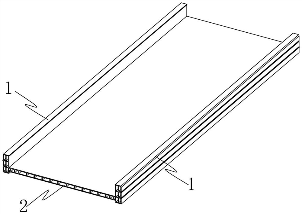
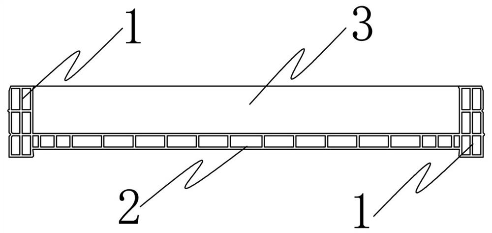
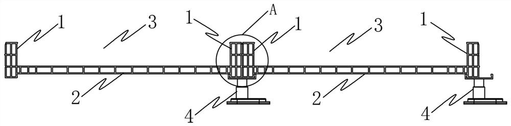
[0032] In the embodiment of the present invention, the substrate is extruded from stone-plastic material, and the hollow stone-plastic board has a good heat insulation effect due to the air layer. The base plate is mainly composed of a plate surface 2 and a rib 1 . The two reinforcing ribs 1 are arranged on both sides of the long side of the...


PUM


Abstract

The invention discloses a floor heating bearing base plate structure. A base plate is mainly composed of reinforcing ribs and a plate face, the two sides of the long edge of the plate face are each provided with one reinforcing rib, the two reinforcing ribs and the plate face form an installation space used for installing a heat preservation plate, a limiting groove and a limiting table are sequentially arranged on the outer side of the reinforcing rib on one side of the long edge of the plate face from top to bottom, a limiting table and a limiting groove are sequentially arranged on the outer side of the reinforcing rib on the other side of the long edge of the plate face from top to bottom, the limiting grooves are matched with the limiting tables to be buckled, the reinforcing ribs ofthe base plate are sequentially arranged, and therefore when the outer sides of the reinforcing ribs are perpendicularly attached, the reinforcing ribs of any two adjacent base plates can be buckled with each other. According to the floor heating bearing base plate structure, the heat preservation plate can be stably installed, the heat preservation plate is buckled in the middle vacant position of the two reinforcing ribs, butt joint buckle structures are arranged between the reinforcing ribs, the combined structures at the bottoms of the reinforcing ribs of a base plate module are used as awhole to be fixed and buckled together through buckle pieces of adjusting feet, and the overall stability of a floor heating plate can be improved.

Description

technical field [0001] The invention relates to the technical field of floor heating substrate installation, in particular to a floor heating load-bearing substrate structure. Background technique [0002] Low-temperature floor heating radiant heating is a heating method that uses the ground inside a building as a heat sink to keep warm and heat the room. [0003] In the prior art, the floor heating laying method is generally a wet laying method, and its structure is divided into a thermal insulation layer, a filling layer, and a balancing layer. The heat insulation layer is located on the surface layer of the floor, and the floor heating pipeline is installed on the upper part of the heat insulation layer, and is fixed on the heat insulation layer with a plastic buckle. The material of the filling layer is cement, which is mixed on site and laid between the floor heating pipelines, with a thickness of 40-60mm; the balance layer is on top of the filling layer, with a thickn...

Claims


Application Information

Patent Timeline
Patent Type & Authority Applications(China)
IPC IPC(8): E04F15/024E04F15/18
CPCE04F15/024E04F15/02464E04F15/18E04F2290/023
Inventor 丁欣欣丁泽成王文广周东珊余文钊武鹏许伟王雨梦张西亮王晓杰
Owner ZHEJIANG YASHA DECORATION
Why Eureka
Try Eureka