
Transmit-receive antenna structure for magnetic resonance coupling wireless power transmission system

A wireless energy transmission, transceiver antenna technology, applied in the direction of collectors, electric vehicles, electrical components, etc., can solve the problems of low edge area of ​​the transmitting antenna, reduced transmission efficiency, no transmission efficiency, etc., to improve the quality factor, reduce the excessive Formation of coupling region, effect of reducing loss resistance

Pending Publication Date: 2021-03-05
CHENGDU SPROUTING TECH CO LTD
View PDF0 Cites 1 Cited by
  • Summary
  • Abstract
  • Description
  • Claims
  • Application Information

AI Technical Summary

Problems solved by technology

The traditional single-coil structure, that is, only one multi-turn square loop coil, is difficult to meet the requirements of stable transmission efficiency when the receiving antenna is placed in different positions within the range of the transmitting antenna. Only when the receiving antenna is placed parallel to the center of the transmitting antenna , its transmission efficiency is high, but when moving to the edge, the transmission efficiency drops very obviously, especially in the edge area of ​​the transmitting antenna is very low
In addition, by adding a reverse winding structure in the multi-turn square loop coil, the problem of the horizontal degree of freedom of the transmitting and receiving antenna can be improved. Most of the positions can meet the daily charging needs, but when the receiving antenna moves to the opposite direction of the transmitting antenna When going to the winding area, the transmission efficiency drops significantly, it can also be said that the transmission efficiency is not high, and it cannot meet the current demand for wireless charging

Method used

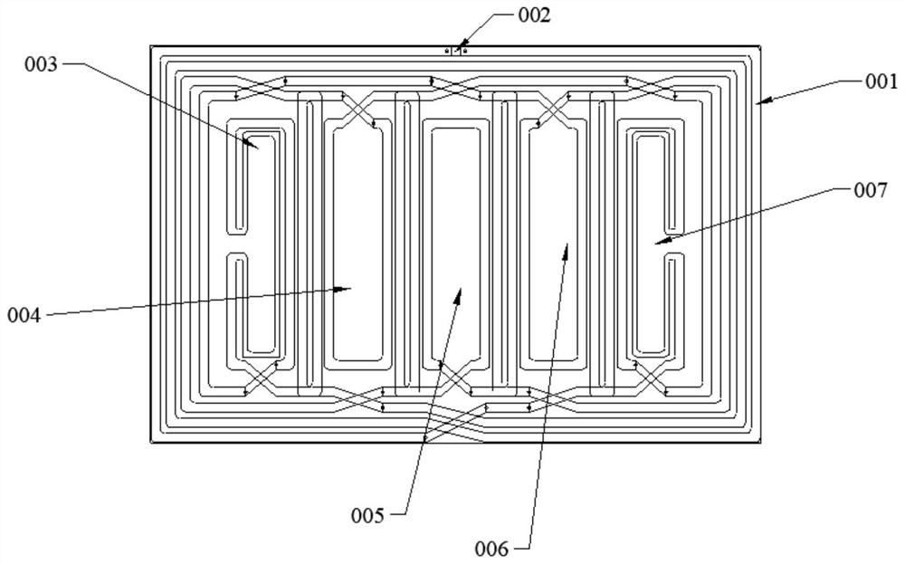
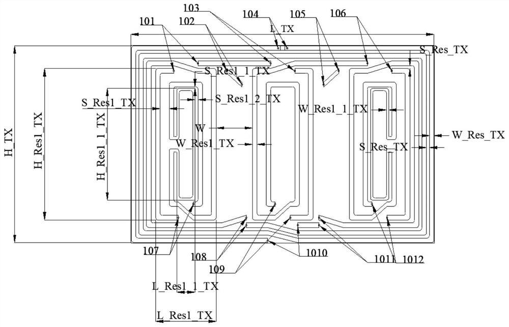
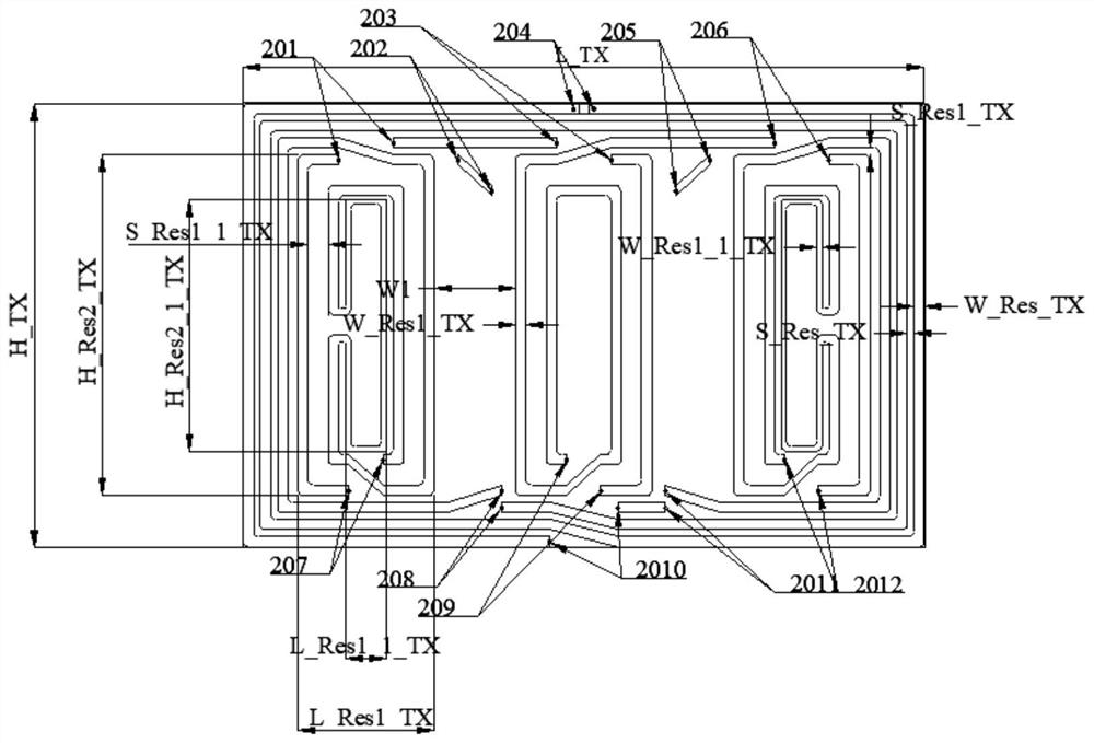

Image

  • Transmit-receive antenna structure for magnetic resonance coupling wireless power transmission system
  • Transmit-receive antenna structure for magnetic resonance coupling wireless power transmission system
  • Transmit-receive antenna structure for magnetic resonance coupling wireless power transmission system

Examples


Embodiment Construction

[0070] The specific embodiments of the present invention are described below so that those skilled in the art can understand the present invention, but it should be clear that the present invention is not limited to the scope of the specific embodiments. For those of ordinary skill in the art, as long as various changes Within the spirit and scope of the present invention defined and determined by the appended claims, these changes are obvious, and all inventions and creations using the concept of the present invention are included in the protection list.

[0071] Embodiments of the present invention will be described in detail below in conjunction with the accompanying drawings.

[0072] Such as figure 1 As shown, a transceiver antenna structure for a magnetic resonance coupled wireless power transmission system, including a transmitting antenna for wireless power transmission and a receiving antenna for wireless power reception;

[0073] The transmitting antenna is a flat p...


PUM

PropertyMeasurementUnit
Lengthaaaaaaaaaa
Widthaaaaaaaaaa
Lengthaaaaaaaaaa

Abstract

The invention discloses a transmit-receive antenna structure for a magnetic resonance coupling wireless power transmission system. Based on a magnetic resonance coupling wireless power transmission scheme, a transmitting antenna employs a series resonance coil array structure with reverse winding, and a receiving antenna employs a resonance coil structure with parasitic coupling. The transmittingantenna is of a flat plate type design and comprises three dielectric layers and four printed circuit structures, and an outermost planar multi-turn coil and a plurality of inner planar multi-turn coils are connected in series to form a closed coil structure. The receiving antenna is also of a flat-plate structure, the front surface is a receiving resonance coil, and the back surface is a parasitic coupling resonance coil. By adopting the series resonance coil array structure with the reverse winding, the transmission efficiency is kept balanced when the receiving antenna moves at different transverse positions in the area of the transmitting antenna, so that the wireless charging and power supply requirements of one or more electronic devices are met when the size difference of the wireless transmitting and receiving ends is large.

Description

technical field [0001] The invention belongs to the technical field of wireless power transmission, and in particular relates to a transceiver antenna structure for a magnetic resonance coupling wireless power transmission system. Background technique [0002] With the continuous development of electronic information technology and automation control technology, various home appliances, electronic consumer products, mobile communication equipment, etc. are widely popularized. Traditional household appliances generally rely on the wired connection between the power cord and the power socket to supply power to the device. Electronic devices with built-in batteries generally also use a wired connection between the charging cable and the power socket, so in daily life In life, wires occupy a lot of our activity space, and subsequently limit the convenience of equipment use. However, in recent years, the research and application of wireless energy transmission technology has rap...

Claims


Application Information

Patent Timeline
IPC IPC(8): H02J50/12H02J50/20H02J50/23H02J50/27H02J7/02
CPCH02J7/02H02J50/12H02J50/20H02J50/23H02J50/27
Inventor 喻易强刘勇罗鑫刘志威张澜潇
Owner CHENGDU SPROUTING TECH CO LTD
Learn More