
Charging method and charging control device for direct-current side short circuit of hybrid converter

A charging method and inverter technology, which are used in output power conversion devices, conversion of AC power input to DC power output, electrical components, etc., can solve problems such as complex charging methods, reduce power and energy requirements, and reduce investment. time, the effect of simplifying the start-up steps

Pending Publication Date: 2021-03-05
XIAN XJ POWER ELECTRONICS TECH +2
View PDF1 Cites 2 Cited by
  • Summary
  • Abstract
  • Description
  • Claims
  • Application Information

AI Technical Summary

Problems solved by technology

[0007] The purpose of the present invention is to provide a charging method and a charging control device for short-circuiting the DC side of a hybrid converter to solve the relatively complicated problem of the existing charging method

Method used


Image

  • Charging method and charging control device for direct-current side short circuit of hybrid converter
  • Charging method and charging control device for direct-current side short circuit of hybrid converter
  • Charging method and charging control device for direct-current side short circuit of hybrid converter

Examples


Embodiment Construction

[0038] The present invention will be described in further detail below in conjunction with the accompanying drawings.

[0039] Method example:

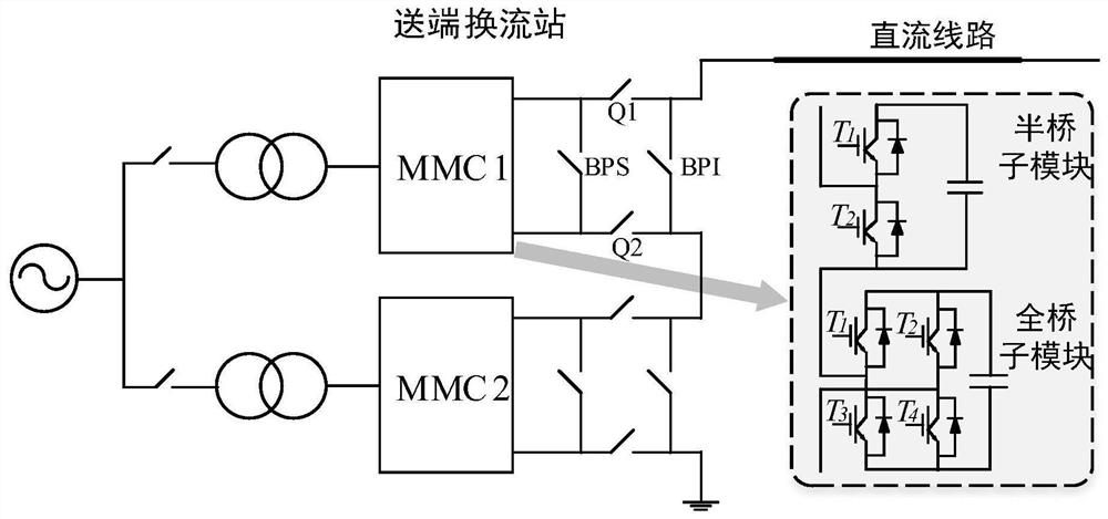
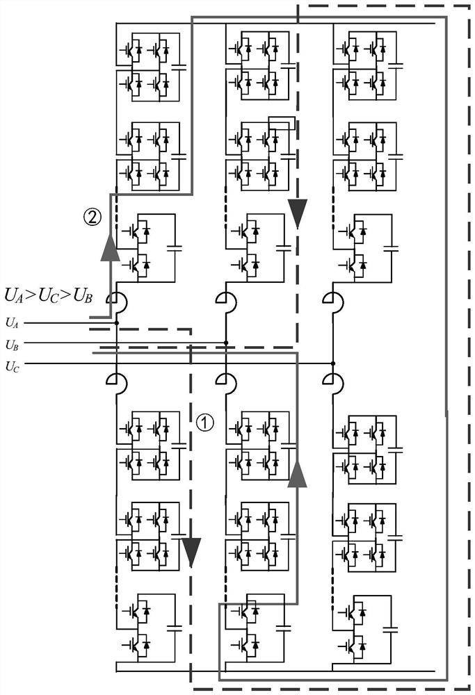
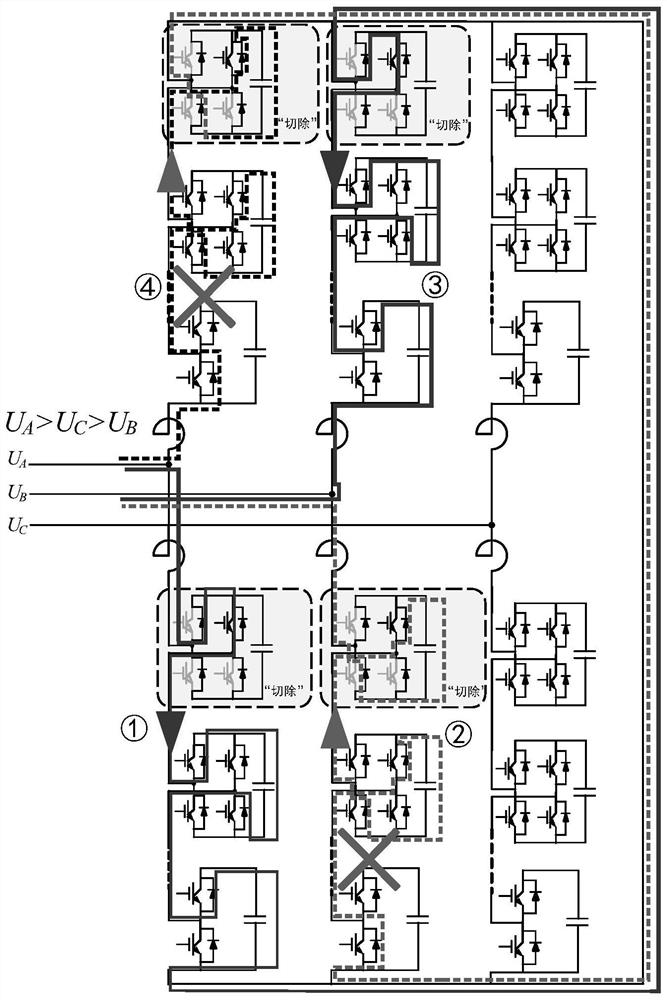
[0040] The invention provides a charging method for a short circuit on the DC side of a hybrid converter, such as figure 2 with image 3 As shown, the sub-module hybrid converter composed of half-bridge sub-modules and full-bridge sub-modules, under the short-circuit condition of the positive and negative busbars on the DC side, the charging method includes a natural charging stage and an active charging stage.

[0041] Natural charging phase:

[0042] In the short-circuit state of the DC side of the converter, put in the soft-start current-limiting resistor, block all sub-modules, and start charging.

[0043] At the beginning of the start-up of the valve group, the power supply of the control circuit of the sub-module cannot be powered, and the sub-module is in a locked state. At this time, the MMC is in the stage of natural chargi...


PUM


Abstract

The invention relates to the field of flexible direct-current power transmission of power systems, in particular to a charging method and a charging control device for direct-current side short circuit of a hybrid converter. The charging method comprises the following steps: under the direct-current side short circuit state of the converter, switching on a soft start current-limiting resistor, locking all sub-modules, and performing charging; and when the charging of the sub-modules of the converter reaches a steady state, cutting off the soft start current-limiting resistor, cutting off a setnumber of sub-modules with higher voltage in each bridge arm of the converter, and keeping the other sub-modules locked. The charging process only comprises a natural charging stage and an active charging stage, and all sub-modules are locked in the natural charging stage; and in the active charging stage, the soft start current-limiting resistor is cut off at the initial moment, and a set numberof sub-modules with higher voltage in each bridge arm are cut off in a specific mode, so that the soft start resistor input time is reduced, the power and energy requirements of the soft start resistor are reduced, and the starting step of the half-bridge full-bridge sub-module hybrid converter under the special working condition of short circuit of direct current positive and negative buses is simplified.

Description

technical field [0001] The invention relates to the field of flexible direct current transmission of power systems, in particular to a charging method and a charging control device for a short circuit on the direct current side of a hybrid converter. Background technique [0002] Compared with the traditional DC transmission technology, the modular multi-level voltage source converter (MMC) has great advantages: no reactive power compensation problem, no commutation failure problem, can supply power for passive systems, and can be independently adjusted Active power and reactive power, low harmonic level, etc. Based on these advantages, MMC has been widely studied since it was proposed, and because the system has low switching frequency, small switching loss, no need for AC filter banks and strong scalability, etc. The advantages make the system applicable to occasions of high DC voltage and high power transmission. [0003] At present, limited by the withstand voltage leve...

Claims


Application Information

Patent Timeline
IPC IPC(8): H02M1/36H02M7/219
CPCH02M1/36H02M7/219
Inventor 平明丽杨美娟王先为牛翀刘启建薛瑞吴金龙
Owner XIAN XJ POWER ELECTRONICS TECH
Learn More