Conductive core plate and manufacturing method

A manufacturing method and conductive core technology, which can be applied in the direction of final product manufacturing, sustainable manufacturing/processing, circuits, etc., can solve the problems that battery arrays are difficult to realize, it is impossible to add 2 rows of batteries experimentally, and the development and implementation of high-efficiency components are limited.

Pending Publication Date: 2020-10-27
JIANGSU SUNPORT POWER CORP LTD
View PDF0 Cites 3 Cited by
  • Summary
  • Abstract
  • Description
  • Claims
  • Application Information

AI Technical Summary

Problems solved by technology

[0003] Conventional photovoltaic modules are mostly 6*10, 6*12, 6*24 even-numbered arrays. In this case, the diodes are easy to wire. Since the market is developing towards large-size modules, 8*10, 8*12, 8* will be designed 24 arrays and other components, but if the actual situation is due to the storage space of the device, it is impossible

Method used


Image

  • Conductive core plate and manufacturing method
  • Conductive core plate and manufacturing method
  • Conductive core plate and manufacturing method

Examples


Embodiment 1

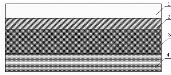
[0035] The present invention is a conductive core board, the conductive core board is an insulating material layer 1, a metal conductive circuit layer 2, an encapsulating adhesive film layer 3, and a backplane layer 4 from top to bottom, and the layers are heated at low temperature bonding;

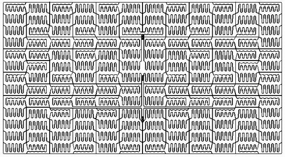
[0036] The metal conductive circuit layer 2 and the encapsulation adhesive film layer 3 are compositely bonded, and a conductive circuit pattern is arranged on the metal conductive circuit layer 2; a number of small holes are arranged on the insulating material layer 1, and the positions of the holes are in line with the The positions of the electrode points on the battery sheet correspond; the conductive circuit diagram is based on the set unit pattern, and the unit pattern is arranged in an array above the battery sheet.

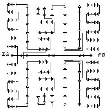
[0037] Further, the unit pattern is that the circuit unit adopts the form of a bell mouth unit and the positive and negative electrodes 6 are opened and divided.

[...

Embodiment 2

[0047] The present invention also provides a method for manufacturing the above-mentioned conductive core board, the method comprising the following steps:

[0048] Copper foil or copper-aluminum foil is used to make metal conductive circuit layer 2, and copper foil or copper-aluminum foil of the same width is combined with packaging film layer 3, and a solid-state laser is used for scribing. Etching specific conductive circuit patterns on copper and aluminum foil;

[0049] Remove the etched copper foil or copper-aluminum foil to form specific conductive channels and insulating channels, that is, conductive circuit diagrams;

[0050] Then punch a number of small holes on the insulating material layer 1, the positions of the holes correspond to the positions of the electrode points on the battery sheet, and isolate the path between the battery sheet and the conductive core board;

[0051] Stack the prepared insulating material layer 1, metal conductive circuit layer 2, encapsu...


PUM


Abstract

The invention discloses a conductive core plate and a manufacturing method. The conductive core plate comprises an insulating material layer, a metal conductive circuit layer, a packaging adhesive film layer and a back plate layer in sequence from top to bottom, wherein all the layers are bonded in a low-temperature heating mode; the metal conductive circuit layer and the packaging adhesive film layer are compounded and bonded, and a conductive circuit diagram is arranged on the metal conductive circuit layer; a plurality of small holes are formed in the insulating material layer, and the positions of the holes correspond to the positions of electrode points on the battery piece; the conductive circuit diagram takes set unit patterns as a basis, and the unit patterns are arranged above thebattery piece in an array manner. According to the invention, the conductive core plate adopts a longitudinal cardinal number column 13*12 half-cut battery arrangement mode, and the cardinal number column battery arrangement is achieved; meanwhile, the number of the batteries connected with the diodes is equal, the installation direction of a junction box is parallel to the short edges of the assembly and is the same as the position of a junction box of a conventional assembly, and if the connection mode is a solder strip assembly, the connection mode is hardly achieved, and the equipment transformation cost can be effectively reduced at the same time.

Description

technical field [0001] The invention relates to the technical field of novel MWT solar cell production equipment, in particular to a conductive core board and a manufacturing method. Background technique [0002] Due to its energy-saving and pollution-reducing features, solar photovoltaic modules are used more and more widely. MWT-type back-contact components are more and more widely used due to their advantages of saving silver paste and high reliability. In response to the development of the market trend, the current photovoltaic industry components are developing in the direction of large area and large size, and MWT technology is no exception, and large area and large size components are also constantly being developed. The main direction of large size and large area is to expand the area of ​​cells. The other direction is to achieve high power by expanding the number of cells arranged. This requires innovation in the arrangement of cells. The industry basically expands...

Claims


Application Information

Patent Timeline
IPC IPC(8): H01L31/044H01L31/048H01L31/05H01L31/18H02S40/34
CPCH01L31/048H01L31/0508H01L31/0516H01L31/188H01L31/044H02S40/34Y02E10/50Y02P70/50
Inventor 张彩霞陈影孙明亮吴仕梁张凤鸣
Owner JIANGSU SUNPORT POWER CORP LTD
Why Eureka
Try Eureka