Meat paste extruding and cutting device
A technology of cutting equipment and minced meat, which is applied in the fields of meat processing, slaughtering, food science, etc., can solve problems such as insecurity, and achieve the effect of being easy to move and ensuring safety
- Summary
- Abstract
- Description
- Claims
- Application Information
AI Technical Summary
Problems solved by technology
Method used
Image
Examples
Embodiment 1
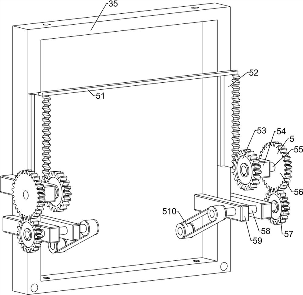
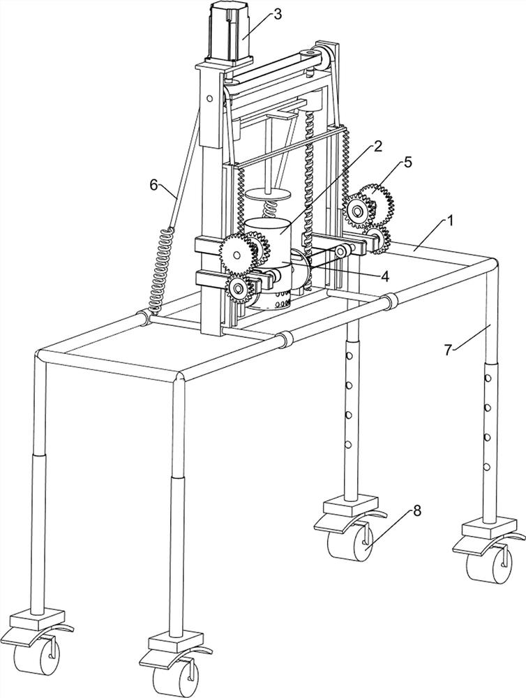
[0026] A kind of minced meat extrusion cutting equipment, such as figure 1 As shown, it includes a ring frame 1, a material barrel 2, a material pressing mechanism 3 and a material cutting mechanism 4, the middle part of the ring frame 1 is connected with a material pressing mechanism 3, and the material pressing mechanism 3 is connected with a material barrel 2, and the material barrel 2 and the material pressing mechanism The 3 parts of the mechanism cooperate to work, the middle part of the pressing mechanism 3 is connected with the cutting mechanism 4, and the bucket 2 is connected with the 4 parts of the cutting mechanism.
[0027] When people need to process the minced meat, people first move the minced meat extruding and cutting equipment to the position for further processing. By manually moving the equipment to a correct position, people manually place the minced meat in the barrel 2, start the pressing The feeding mechanism 3 automatically squeezes the minced meat. T...
Embodiment 2
[0029] On the basis of Example 1, such as figure 2 As shown, the pressing mechanism 3 includes a bracket 35, a first support plate 32, a servo motor 31, a screw mandrel 33, a first transmission assembly 34, a slider 36, a first connecting rod 37, a pressing plate 38 and a chute 39, and the ring Frame 1 middle part is provided with support 35, and the upper left side of support 35 is provided with first support plate 32, and the top of first support plate 32 is provided with servomotor 31, and all left and right sides in support 35 are connected with screw mandrel 33 in rotation, servomotor 31 The output shaft is connected to the left screw rod 33, and the other ends of the screw rods 33 on both sides are rotationally connected to the inner lower part of the bracket 35. A first transmission assembly 34 is arranged between the upper parts of the screw rods 33 on both sides, and the screw rods 33 on both sides The average screw type is provided with a slider 36, the slider 36 is...
Embodiment 3
[0032] On the basis of Example 2, such as image 3 , Figure 4 , Figure 5 , Figure 6 , Figure 7 and Figure 8As shown, the material cutting mechanism 4 includes a support 47, a first rotating shaft 46, a rotating disk 45, a fixed block 44, a rod groove 43, a push rod 42, and an annular cutting plate 41, and the middle part of the inner side of the support 35 is symmetrically provided with a support 47, the support 47 is located on the left and right sides of the material barrel 2, the upper part of the support 47 on both sides is provided with a first rotating shaft 46, the inner side of the support 47 on both sides is provided with a turntable 45, and the eccentric position of the inner side of the turntable 45 is provided with a fixed block 44, fixed block 44 internal slide type is provided with rod groove 43, and the outside middle part of rod groove 43 is connected with push rod 42, and bucket 2 outer wall sliding type is provided with annular cutting plate 41, and ...
PUM
 Abstract
Description
Claims
Application Information
 - R&D
- Intellectual Property
- Life Sciences
- Materials
- Tech Scout
- Unparalleled Data Quality
- Higher Quality Content
- 60% Fewer Hallucinations
Browse by: Latest US Patents, China's latest patents, Technical Efficacy Thesaurus, Application Domain, Technology Topic, Popular Technical Reports.
© 2025 PatSnap. All rights reserved.Legal|Privacy policy|Modern Slavery Act Transparency Statement|Sitemap|About US| Contact US: help@patsnap.com


