Waste recovery punching device

A punching device, waste recycling technology, applied in the direction of boring/drilling, drilling/drilling equipment, maintenance and safety accessories, etc., can solve the problems of inconvenient waste, recycling, etc.

Active Publication Date: 2021-03-09
德清县宝华氟塑料工贸有限公司
View PDF6 Cites 0 Cited by
  • Summary
  • Abstract
  • Description
  • Claims
  • Application Information

AI Technical Summary

Problems solved by technology

[0003] The purpose of the present invention is to provide a waste material recycling punching device to solve the technical problem that it is inconvenient to recycle the waste material after punching the plate when punching the plate

Method used


Image

  • Waste recovery punching device
  • Waste recovery punching device
  • Waste recovery punching device

Examples


Embodiment Construction

[0026] The technical solutions of the present invention will be clearly and completely described below with reference to the accompanying drawings. Obviously, the described embodiments are a part of the embodiments of the present invention, but not all of the embodiments.

[0027] The components of the embodiments of the invention generally described and shown in the drawings herein may be arranged and designed in a variety of different configurations. Thus, the following detailed description of the embodiments of the invention provided in the accompanying drawings is not intended to limit the scope of the invention as claimed, but is merely representative of selected embodiments of the invention.

[0028] Based on the embodiments of the present invention, all other embodiments obtained by those of ordinary skill in the art without creative efforts shall fall within the protection scope of the present invention.

[0029]In the description of the present invention, it should be...


PUM


Abstract

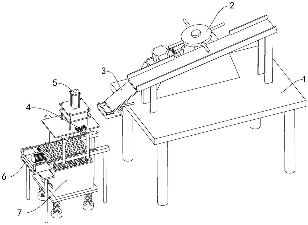
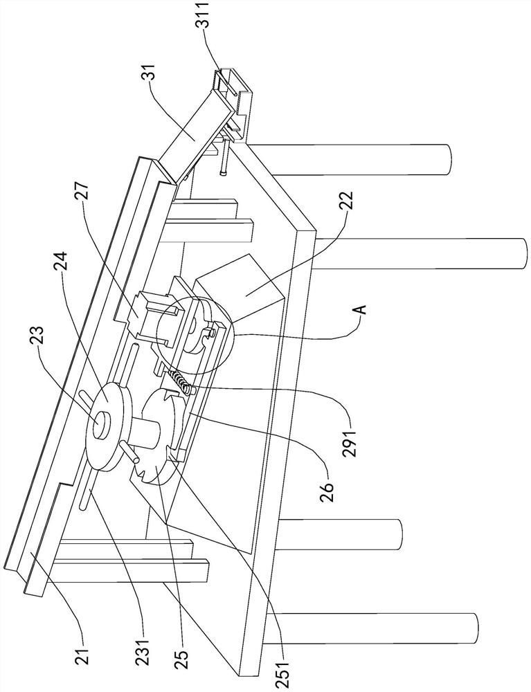
The invention relates to the technical field of punching equipment, and discloses a waste recovery punching device. The device comprises a workbench, a feeding assembly, a pushing assembly, a clampingassembly, a drilling assembly, an overturning assembly and a recycling assembly, the feeding assembly is arranged at the top end of the workbench, and the pushing assembly is located at one side of the workbench; and one end of the pushing assembly is fixedly connected with one end of the feeding assembly, the clamping assembly is located at one side of the pushing assembly, the drilling assemblyis arranged above the clamping assembly, the overturning assembly is arranged below the clamping assembly, and the recycling assembly is located below the overturning assembly. By means of the wasterecovery punching device, waste generated after plate punching can be recycled, and personnel can conveniently treat the waste.

Description

technical field [0001] The invention relates to the technical field of punching equipment, in particular to a punching device for recycling waste. Background technique [0002] Punching refers to adapting to different needs, specifically: character-eight holes, hexagonal holes, punching plates, long holes, square holes, round holes, punching plate nets, triangular holes, etc., pipe punching and sheet punching In comparison, although there are many similarities in terms of deformation properties, deformation characteristics, etc., because the pipe is a hollow cylindrical blank, the pipe wall that the convex and concave molds contact during punching is a solitary surface instead of a flat surface like a plate. Therefore, it is necessary to take special technological measures and the structure of the mold. When punching the plate in the prior art, it is inconvenient to recycle the waste after the plate is punched. SUMMARY OF THE INVENTION [0003] The purpose of the present ...

Claims


Application Information

Patent Timeline
Patent Type & Authority Applications(China)
IPC IPC(8): B23B41/00B23Q7/02B23Q7/06B23Q11/00
CPCB23B41/00B23Q7/02B23Q7/06B23Q11/0042Y02P70/10
Inventor 蔡斌
Owner 德清县宝华氟塑料工贸有限公司
Why Eureka
Try Eureka