Novel steel plate machining equipment
A machining and steel plate technology, applied in the field of new steel plate machining equipment, can solve the problems of waste of steel plate raw materials, pressure exerted by punching machines, waste of manpower, etc., and achieve the effect of accurate drilling positions.
- Summary
- Abstract
- Description
- Claims
- Application Information
AI Technical Summary
Problems solved by technology
Method used
Image


Examples
Embodiment 1
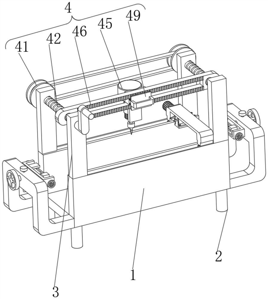
[0031] Example 1, such as Figure 1-9As shown, the present invention provides a new type of steel plate machining equipment, including a workbench 1 and a punching device 4, four support legs 2 are fixedly installed on the bottom of the workbench 1, and a side of the workbench 1 away from the support legs 2 is provided There is an accommodating groove, and four connecting columns 3 are fixedly installed on the side of the workbench 1 close to the accommodating groove.
[0032] Let's talk about the specific setting and effect of its punching device 4, derusting device 5 and auxiliary device 6 in detail below.
[0033] Such as image 3 with Figure 4 As shown, four connecting columns 3 are in groups of two, and the surface of each group of connecting columns 3 is provided with a punching device 4, and the punching device 4 includes two first screw rods 42, and the surfaces of the two first screw rods 42 all penetrate Two sets of connecting columns 3, and the surface of the fi...
Embodiment 2
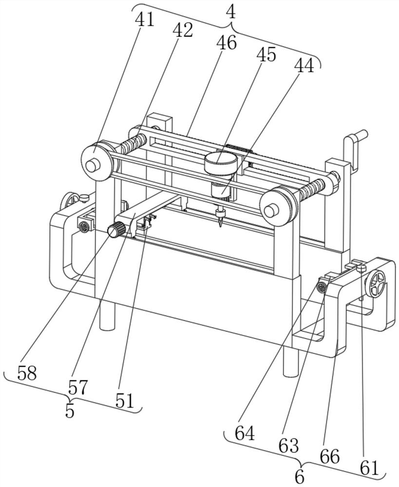
[0037] Embodiment 2, on the basis of embodiment 1, as Image 6 with Figure 7 As shown, the workbench 1 is provided with two rectangular grooves near the side of the holding groove, and the inside of the two rectangular grooves is provided with a derusting device 5. The derusting device 5 includes two slide blocks 56, and the two slide blocks 56 The surfaces are respectively slidingly connected with two rectangular grooves, the surfaces of the two sliders 56 are fixedly connected with a second telescopic rod, and the end of the second telescopic rod away from the slider 56 is fixedly connected with a connecting frame 57, and the second screw rod 59 The surface is covered with a second spring 55, and the two ends of the second spring 55 are fixedly connected to the slider 56 and the connecting frame 57 respectively. The connecting frame 57 is a "U"-shaped structure, and between the two arms of the "U"-shaped connecting frame 57 Rotationally connected with a second screw rod 59...
PUM
 Abstract
Description
Claims
Application Information
 - Generate Ideas
- Intellectual Property
- Life Sciences
- Materials
- Tech Scout
- Unparalleled Data Quality
- Higher Quality Content
- 60% Fewer Hallucinations
Browse by: Latest US Patents, China's latest patents, Technical Efficacy Thesaurus, Application Domain, Technology Topic, Popular Technical Reports.
© 2025 PatSnap. All rights reserved.Legal|Privacy policy|Modern Slavery Act Transparency Statement|Sitemap|About US| Contact US: help@patsnap.com