
Cleaning equipment for treating electroplated copper balls

A technology for cleaning equipment and electroplating copper balls, which is applied in the electrolysis process, electrolysis components, fixed filter element filters, etc., can solve the problems of low cleaning efficiency, strong corrosion, general filtering effect, etc., to ensure safety and good air tightness performance and safety enhancement

Active Publication Date: 2021-03-09
深圳市鑫达辉软性电路科技有限公司
View PDF8 Cites 2 Cited by
  • Summary
  • Abstract
  • Description
  • Claims
  • Application Information

AI Technical Summary

Problems solved by technology

[0008] The purpose of the present invention is to provide a cleaning device for electroplating copper balls to solve the problems in the background technology that the filtering effect is general and it is impossible to isolate the copper balls from the solution while filtering. The small copper balls that meet the specifications are mostly corrosive because the solution is mixed with hydrogen peroxide and sulfuric acid. The service life of the internal components is short, the copper balls cannot fully contact the solution, and the cleaning efficiency is low. The contact of the solution produces a chemical reaction, the safety of the staff cannot be guaranteed, and the internal components cannot be operated and cannot be detected at the first time, etc.

Method used


Image

  • Cleaning equipment for treating electroplated copper balls
  • Cleaning equipment for treating electroplated copper balls
  • Cleaning equipment for treating electroplated copper balls

Examples


Embodiment Construction

[0035] The following will clearly and completely describe the technical solutions in the embodiments of the present invention with reference to the accompanying drawings in the embodiments of the present invention. Obviously, the described embodiments are only some, not all, embodiments of the present invention. Based on the embodiments of the present invention, all other embodiments obtained by persons of ordinary skill in the art without making creative efforts belong to the protection scope of the present invention.

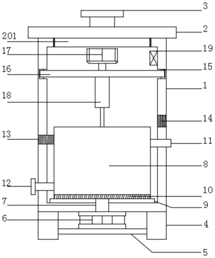
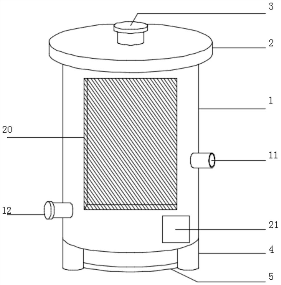
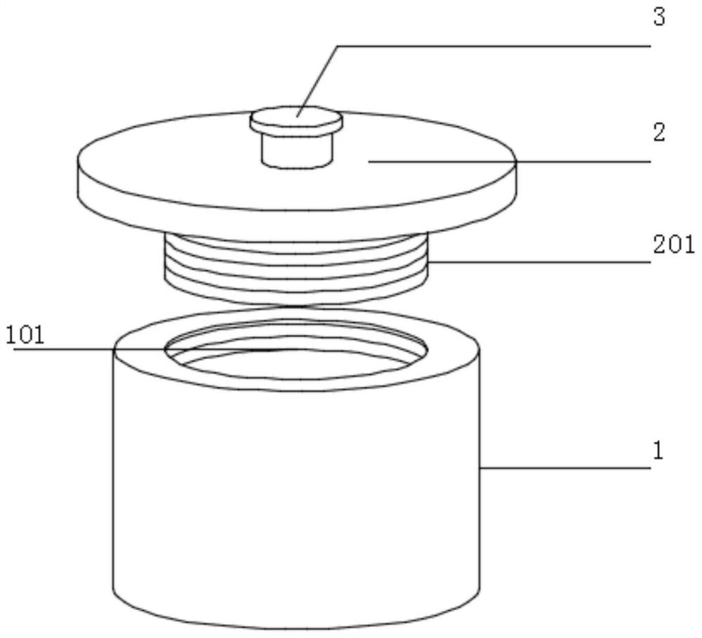
[0036] see Figure 1-7 , in this embodiment: including the equipment main body 1, the top of the equipment main body 1 is provided with a cover body 2, the upper end of the cover body 2 is provided with an air valve 3 at the center of the circle, the bottom of the equipment main body 1 is provided with three sets of legs 4, and the three sets of legs 4 The interframe is provided with a connecting frame 5, the upper end of the connecting frame 5 is located betw...


PUM


Abstract

The invention discloses cleaning equipment for treating electroplated copper balls. The cleaning equipment comprises an equipment body; a cover body is arranged at the top of the equipment body; an air valve is arranged at the circle center of the upper end of the cover body; three sets of supporting legs are arranged at the bottom of the equipment body; a connecting frame is erected among the three sets of supporting legs; a hydraulic cylinder is arranged on the upper end face of the connecting frame and located among the supporting legs; a hydraulic rod is arranged in the hydraulic cylinderin a penetrating mode; a containing base is arranged at the bottom end in the equipment body; a cleaning cylinder is arranged at the upper end of the containing base; a filtering device is arranged atthe bottom end in the cleaning cylinder; a liquid inlet pipe is arranged at one side of the upper end of the cleaning cylinder, and a liquid outlet pipe is arranged at the other side of the bottom ofthe cleaning cylinder; a feeding hole is formed in the upper end of the same side of the liquid outlet pipe; and a discharging hole is formed in the bottom of the same side of the liquid inlet pipe.According to the cleaning equipment for treating the electroplated copper balls, a stirring device is arranged, and a stirring paddle spirally clings to the upper end of a rotating shaft, so that a solution can be better driven to spirally rotate, the copper balls can be in more sufficient contact with the solution, and the cleaning efficiency of the equipment is prompted.

Description

technical field [0001] The invention relates to the technical field of copper plating cylinder maintenance, in particular to a cleaning device for electroplating copper balls. Background technique [0002] In the field of electroplating, the maintenance of the copper plating cylinder needs to replace the potion, clean the copper ball, anode bag, titanium mesh, etc., especially the copper ball maintenance uses the micro-etching solution configured with hydrogen peroxide and sulfuric acid to remove the anode film. Do copper ball cleaning equipment for this. [0003] There are following defects or problems in the prior art: [0004] 1. The existing cleaning machine has a general filtering effect and cannot isolate copper balls from the solution while filtering small copper balls that do not meet the specifications; [0005] 2. The existing cleaning machine is highly corrosive because the solution is mostly mixed with hydrogen peroxide and sulfuric acid, and the service life o...

Claims


Application Information

Patent Timeline
Patent Type & Authority Applications(China)
IPC IPC(8): C25D21/08C23G3/00B01D29/03
CPCC25D21/08C23G3/00B01D29/03
Inventor 黄栋
Owner 深圳市鑫达辉软性电路科技有限公司
Learn More