Foundation pit supporting structure
A technology of foundation pit support and split structure, which is applied in foundation structure engineering, sheet pile wall, excavation and other directions, can solve the problems of low construction efficiency, large impact on construction period, long setting time, etc. Effect
- Summary
- Abstract
- Description
- Claims
- Application Information
AI Technical Summary
Problems solved by technology
Method used
Image


Examples
Embodiment 1
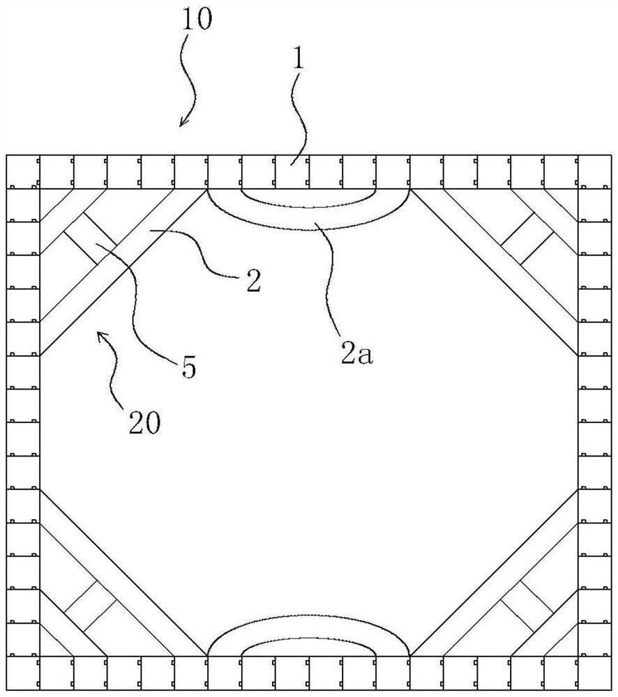
[0057] Such as figure 1 and figure 2 As shown, the present embodiment provides a support structure for a foundation pit, including a retaining wall 10, which has more than two prefabricated retaining members 1 spliced with each other, and a supporting beam system 20, at least one end of which tendons are And / or part of the embedded parts are mechanically connected and fixed to the embedded parts of the prefabricated enclosure member 1, and the support beam system 20 is arranged substantially horizontally.
[0058] In above-mentioned structure, utilize the enclosure wall 10 that the prefabricated enclosure member 1 that splices together constitutes, the enclosure wall 10 that forms can be used as the outer wall of building various underground buildings such as multi-storey basement, underground railway, underground commercial street, During follow-up construction, it only needs to be modified on the basis of the retaining wall 10, and waterproofing and other treatments can ...
Embodiment 2
[0072] In this embodiment, the same reference numerals are assigned to the same parts as those in Embodiment 1, and the same text descriptions are omitted.
[0073] The difference between this embodiment and Embodiment 1 lies in that the structural forms of the connectors are different.
[0074] In addition, because the connector 3 takes various measures to ensure the dimensional accuracy and manufacturing accuracy of the components during the manufacturing process, the dimensional error of the connector 3 and the position error of each component in the connector 3 are still inevitable, and the gap between components The matching accuracy error is also unavoidable (such as thread clearance error); on the other hand, in order to ensure the smooth progress of the assembly, a certain degree of clearance must be left between the connectors 3 to avoid collisions during the assembly process, and these clearances The existence of also makes there is an inevitable length error between...
Embodiment 3
[0085] In this embodiment, the same reference numerals are assigned to the same parts as in Embodiment 2, and the same text descriptions are omitted.
[0086] The difference between this embodiment and Embodiment 2 lies in that the structural forms of the connectors are different.
[0087] Such as Figure 9 As shown, in this embodiment, the length adjustment part 35 is a clamping adjustment cavity 35b, the butt end of one of the butt joint piece 34 and the connection part 31 has a thick part 35d with a diameter larger than the main body, and the other butt end is provided with a The body passes through the through hole 35e with a minimum diameter smaller than the thick part 35d, the diameter of the clamping adjustment cavity 35b is larger than the maximum outer diameter of the thick part 35d, and the axial length of the clamping adjustment cavity 35b is greater than the axial length of the thick part 35d, It is used for adjusting the mating length of the connecting member 34 ...
PUM
 Abstract
Description
Claims
Application Information
 - R&D
- Intellectual Property
- Life Sciences
- Materials
- Tech Scout
- Unparalleled Data Quality
- Higher Quality Content
- 60% Fewer Hallucinations
Browse by: Latest US Patents, China's latest patents, Technical Efficacy Thesaurus, Application Domain, Technology Topic, Popular Technical Reports.
© 2025 PatSnap. All rights reserved.Legal|Privacy policy|Modern Slavery Act Transparency Statement|Sitemap|About US| Contact US: help@patsnap.com