Water chilling unit ejector performance simulation test system and test method

A simulation test and chiller technology, which is applied in the testing of machines/structural components, instruments, measuring devices, etc., can solve problems such as insufficient oil return capacity, waste of after-sales costs, and fluctuations in ejection performance, so as to reduce testing costs and eliminate The effect of high volatility and guaranteed reliability

Pending Publication Date: 2021-03-09
GREE ELECTRICHEFEI +1
View PDF0 Cites 0 Cited by
  • Summary
  • Abstract
  • Description
  • Claims
  • Application Information

AI Technical Summary

Problems solved by technology

Commonly used injectors are composed of inlet tubes, outlet tubes, and jet tubes. The components are mostly welded or threaded. At present, the assembly process mainly relies on visual inspection of the size of the components. In actual production, it is difficult to find subtle dimensional deviations in the internal channels. It is very easy to cause large fluctuations in ejector performance, resulting in insufficient oil return capacity when the whole machine is running under low pressure differential and other loads. In severe cases, the unit is frequently protected and shut down, and the ejector must be replaced repeatedly to solve the problem, resulting in waste of process production and after-sales costs

Method used


Image

  • Water chilling unit ejector performance simulation test system and test method
  • Water chilling unit ejector performance simulation test system and test method
  • Water chilling unit ejector performance simulation test system and test method

Examples


Embodiment Construction

[0029] The present invention will be further described below in conjunction with accompanying drawing.

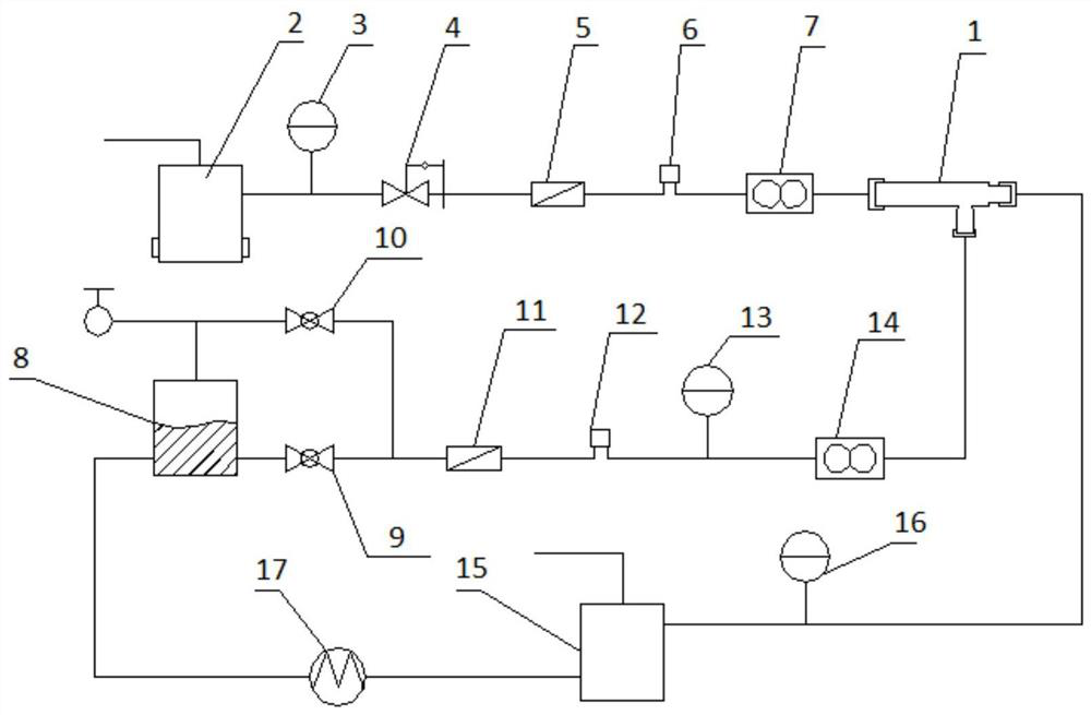
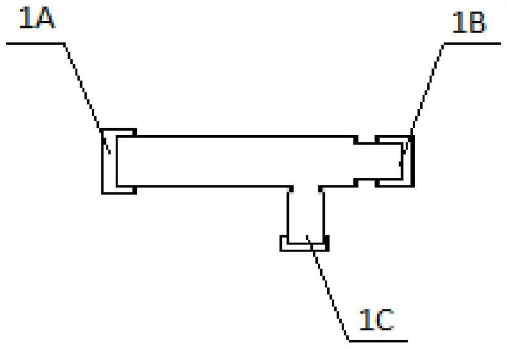
[0030] figure 1 It is a structural schematic diagram of the test system of the present application. Such as figure 1 As shown, the test system includes an injector 1 to be tested, a jet flow part, a jet flow part to be tested and a control part (not shown), wherein the injector 1 to be tested includes an introduction tube 1A, an outlet tube 1B and a jet tube 1C( figure 2 ), the part of the drawing jet and the part of the drawn jet are connected to the introduction pipe 1A and the jet pipe 1C of the injector 1 to be tested through, for example, a cylinder.

[0031] Specifically, the jet flow part includes a simulated condensing device 2 and a first pressure sensor 3 and a first electronic pressure regulating valve which are sequentially arranged on the pipeline connecting the simulated condensing device 2 and the introduction pipe 1A of the injector 1 to be tested. 4. T...


PUM


Abstract

The invention provides a water chilling unit ejector performance simulation test system and test method. The test system comprises an ejector to be detected, an ejection flow part, an ejected flow part and a control part. The jet flow part comprises a simulated condensation device, a first pressure sensor, a first electronic pressure regulating valve, a first filter, an electronic expansion valveand a first flow meter, and the jetted flow part comprises a simulated evaporation device, a self-selected working condition mode electromagnetic valve, a second filter, an electronic expansion valve,a second pressure sensor and a second flow meter; and the control part is used for receiving the numerical values sent by the first flow meter and the second flow meter and calculating the ejection coefficient of the ejector to be detected according to the collected gas flow and the second flow. By means of the system, the performance of the single ejector can be tested under different working condition pressures of the condenser and the evaporator, large fluctuation of the ejection performance of the ejector is eliminated, and the reliability of the oil return efficiency of the whole machineis guaranteed.

Description

technical field [0001] The invention relates to the field of performance testing of chiller components, and more particularly, to a chiller ejector performance simulation testing system and testing method. Background technique [0002] In the oil return system of the chiller, the ejector is widely used as a key component because of its simple structure and flexible installation. Commonly used ejectors are composed of inlet tubes, outlet tubes, and jet tubes. Most of the components are welded or threaded. At present, the assembly process mainly relies on visual inspection of the size of the components. In actual production, it is difficult to find subtle dimensional deviations in the internal channels. It is very easy to cause large fluctuations in ejector performance, resulting in insufficient oil return capacity when the whole machine is running under low pressure differential and other loads. In serious cases, the unit is frequently shut down for protection, and the ejecto...

Claims


Application Information

Patent Timeline
Patent Type & Authority Applications(China)
IPC IPC(8): G01M99/00
CPCG01M99/005
Inventor 俞孟春李敏王帆单维朋朱顺
Owner GREE ELECTRICHEFEI
Why Eureka
Try Eureka