Oscilloscope for electronic engineering measurement
A technology of electronic engineering and oscilloscope, applied in the direction of measuring device, measuring electrical variable, measuring device casing, etc., can solve the problems of high temperature heating of internal components, difficult measurement of electronic engineering, easy damage of internal components, etc. High, solve the effect of poor shock absorption, easy to carry
- Summary
- Abstract
- Description
- Claims
- Application Information
AI Technical Summary
Problems solved by technology
Method used
Image
Examples
Embodiment 1
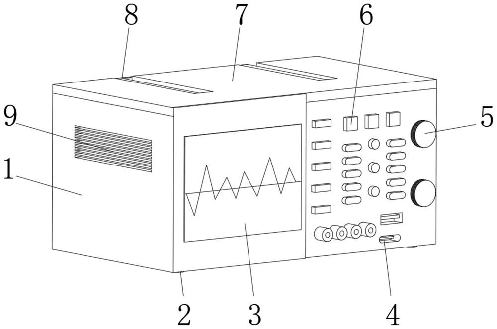
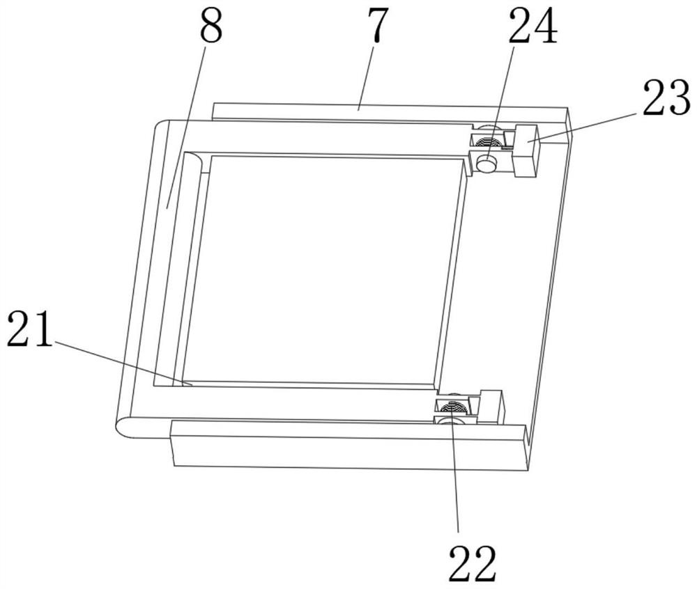
[0029] see Figure 1-4 , an oscilloscope for electronic engineering measurement, comprising an oscilloscope main body 1, a display 3 is fixedly connected to the front side of the oscilloscope main body 1, a button 6 is provided on one side of the display 3, an adjuster 5 is provided on one side of the button 6, and an adjuster 5 is provided on one side of the button 6 The bottom is provided with a data transmission port 4, the top of the oscilloscope main body 1 is fixedly connected with a top cover 7, and the top of the top cover 7 is provided with a placement groove 21, and a handle 8 is provided inside the placement groove 21, and one end of the handle 8 is connected with a pin for rotation 24. The outer wall of the pin shaft 24 is provided with a spring 22, and one end of the spring 22 is fixedly connected with a fixture 23, and one side of the main body 1 of the oscilloscope is provided with a ventilation window 9.
[0030] In this embodiment, through the cooperative arra...
Embodiment 2
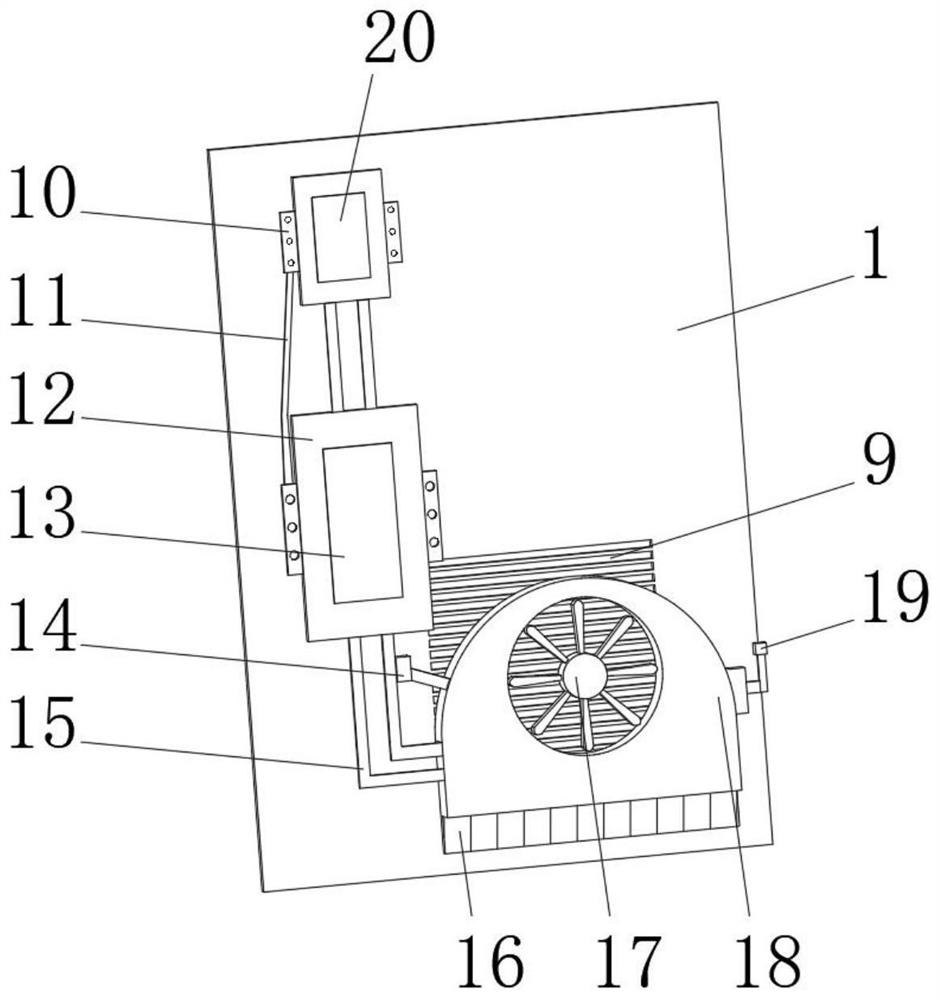
[0032] see figure 1 and 2 , this embodiment is further optimized on the basis of Embodiment 1, specifically, one side of the ventilation window 9 is provided with a casing 18, the casing 18 is arranged inside the oscilloscope main body 1, and the bottom end of the casing 18 is fixedly connected with Fin16.
[0033] Specifically, a copper pipe 15 is fixedly connected to one side of the casing 18 , and a connection wire 19 is fixedly connected to the other side of the casing 18 , and a fan 17 is provided inside the casing 18 .
[0034] Specifically, one end of the copper pipe 15 is fixedly connected to the heat conduction base 12 , the top end of the heat conduction base 12 is fixedly connected to the first heat conduction medium 13 , and one side of the copper pipe 15 is fixedly connected to the vapor chamber 14 .
[0035] Specifically, there are multiple copper pipes 15, and there are two heat-conducting bases 12, the top of one heat-conducting base 12 is fixedly connected w...
Embodiment 3
[0038] see Figure 4 , this embodiment is optimized as follows on the basis of Example 1 or Example 2. Specifically, the bottom end of the oscilloscope main body 1 is provided with a groove, the bottom end of the groove is slidably connected with a fixed base 2, and the top end of the fixed base 2 A crossbeam 27 is fixedly connected.
[0039] Specifically, both ends of the beam 27 are movably connected with rollers 26 , the middle part of the top end of the beam 27 is fixedly connected with a second shock absorber 29 , and the top of the second shock absorber 29 is fixedly connected with a two-way connector 30 .
[0040] Specifically, a baffle 28 is movably connected to the inside of the two-way connector 30 , one side of the baffle 28 is fixedly connected to the first shock absorber 25 , and the roller 26 is rollingly connected to the other side of the baffle 28 .
[0041] In this embodiment, through the cooperation between the fixed base 2, the beam 27, the baffle plate 28,...
PUM
 Abstract
Description
Claims
Application Information
 - R&D
- Intellectual Property
- Life Sciences
- Materials
- Tech Scout
- Unparalleled Data Quality
- Higher Quality Content
- 60% Fewer Hallucinations
Browse by: Latest US Patents, China's latest patents, Technical Efficacy Thesaurus, Application Domain, Technology Topic, Popular Technical Reports.
© 2025 PatSnap. All rights reserved.Legal|Privacy policy|Modern Slavery Act Transparency Statement|Sitemap|About US| Contact US: help@patsnap.com


