Dynamic sculpture provided with driving mechanism

A driving mechanism and dynamic technology, applied in the field of decorative sculpture, can solve the problems of inability to perform multiple movements at the same time, many restrictions, and few types of dynamic sculptures.

Pending Publication Date: 2021-03-12
南京筑新科技有限公司
View PDF7 Cites 0 Cited by
  • Summary
  • Abstract
  • Description
  • Claims
  • Application Information

AI Technical Summary

Problems solved by technology

[0003] However, the existing dynamic sculptures have few types, many restrictions, and large limitations. They cannot perform multiple movements at the same time, and there is no specific light to match the sculptures when viewing, resulting in insufficient viewing and loss of the meaning of dynamic sculptures. Therefore, we propose A dynamic sculpture with a driving mechanism to solve the above-mentioned problems

Method used


Image

  • Dynamic sculpture provided with driving mechanism
  • Dynamic sculpture provided with driving mechanism
  • Dynamic sculpture provided with driving mechanism

Examples


Embodiment 1

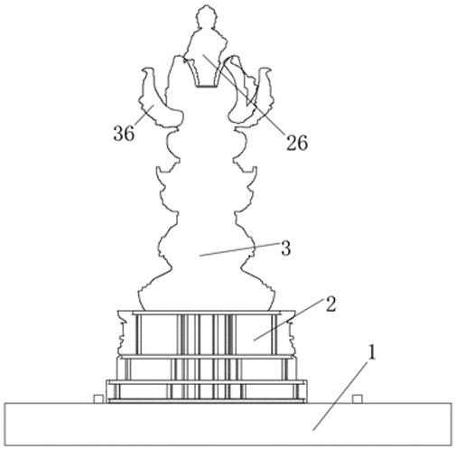
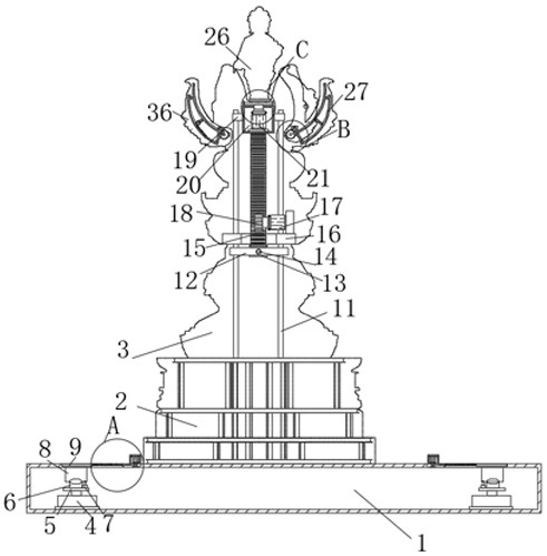
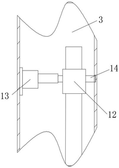
[0029] refer to Figure 1-6 , a dynamic sculpture provided with a driving mechanism, comprising a base 1, the top of the base 1 is provided with two lifting openings, the inside of the base 1 is provided with two lighting components, and the inner wall of the top of the base 1 is provided with two lifting openings that block the two lifting openings. A shielding assembly, the top of the base 1 is fixedly connected with a steel frame 2, the top of the steel frame 2 is fixedly connected with a metal outer skin 3, the inner walls of both sides of the metal outer skin 3 are fixedly connected with a fixed plate 16, and the top of the fixed plate 16 is fixedly connected There is a lifting assembly, the inside of the fixed plate 16 is provided with an entrance and exit, the bottom inner wall of the metal outer skin 3 is slidably connected with a lifting box 20, the bottom inner wall of the lifting box 20 is fixedly connected with a second motor 21, and the output shaft of the second m...

Embodiment 2

[0031]This embodiment is improved on the basis of Embodiment 1: the two lighting components include two hydraulic cylinders 4 fixedly connected to the inner wall of the bottom of the base 1, the piston rod of the hydraulic cylinder 4 is fixedly connected to a mounting plate 5, and the top of the mounting plate 5 is fixed Connected with a rotating rod 6, the top of the rotating rod 6 is rotatably connected with a spotlight 8, the top of the mounting plate 5 is fixedly connected with an electric telescopic rod 7, and the top of the electric telescopic rod 7 is rotatably connected with the bottom of the spotlight 8, and the spotlight 8 is located at the bottom of the lifting port. Directly below, the two shielding assemblies include a fourth motor 32 fixedly connected to the top of the base 1 , the output shaft of the fourth motor 32 is fixedly connected to a third rotating shaft 33 , one end of the third rotating shaft 33 runs through the base 1 and connects to one side of the bas...


PUM


Abstract

The invention belongs to the technical field of decorative sculptures, particularly relates to a dynamic sculpture provided with a driving mechanism, and aims to solve the problems that existing dynamic sculptures are few in variety, many in limitation, large in limitation and incapable of doing various motions at the same time, and the problem that no specific light is provided for cooperating with sculptures during viewing, so that the ornamental value is insufficient. According to the scheme, thedynamic sculpture includes a base, two lifting openings are formed in the top of the base, two illumination assemblies are arranged in the base, two shielding assemblies for shielding the two lifting openings are arranged on the inner wall of the top of the base, and a steel framework is fixedlyconnected to the top of the base. In the invention, opening and closing of the dynamic lotus petals and lifting and rotating of the Buddha statue can be conducted at the same time through the first motor, the second motor and the third motor, so that the form is novel, the connotation of dynamic deductive sculpture is better interpreted, people can more clearly view the Buddha statue through thespotlight, and the viewing effect is improved.

Description

technical field [0001] The invention relates to the technical field of decorative sculptures, in particular to a dynamic sculpture provided with a driving mechanism. Background technique [0002] Sculpture refers to ornamental objects and monuments carved to beautify the city or used for commemorative significance, with a certain meaning, symbol or pictogram. Sculpture is a kind of plastic arts. The production and development of sculpture are closely related to human production activities. At the same time, it is directly affected by social ideologies such as religion and philosophy in various ages. When humans were still in the Paleolithic Age, primitive stone carvings and bone carvings appeared. Sculpture is a relatively permanent art. The traditional idea is that sculpture Sculpture is a static, visible, touchable three-dimensional object that reflects reality by resorting to visual spatial images through sculpture, so it is considered to be the most typical plastic arts,...

Claims


Application Information

Patent Timeline
Patent Type & Authority Applications(China)
IPC IPC(8): A47G33/00
CPCA47G33/00
Inventor 王兆东员浩阳刘海滨张雨婷
Owner 南京筑新科技有限公司
Why Eureka
Try Eureka