Strengthening equipment for screw hole in automobile part
A technology of auto parts and equipment, applied in the field of auto parts screw hole strengthening equipment, can solve the problems of reducing structural strength, etc., and achieve the effect of convenient cleaning and cleaning
- Summary
- Abstract
- Description
- Claims
- Application Information
AI Technical Summary
Problems solved by technology
Method used
Image
Examples
Embodiment 1
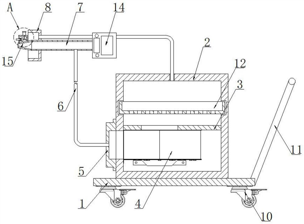
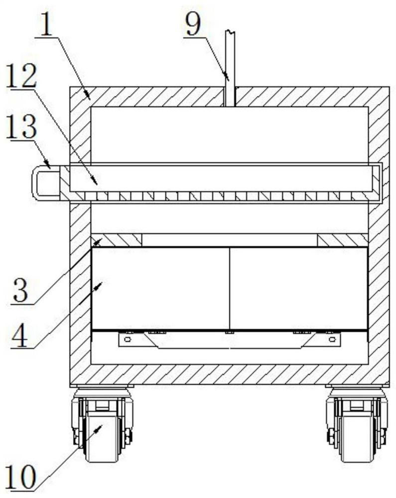
[0024] refer to Figure 1-2 , a screw hole strengthening device for auto parts, comprising a base plate 1, universal wheels with brakes 10 are fixedly connected to the four corners of the lower surface of the base plate 1, and push rods 11 are fixedly connected to the side of the base plate 1.
[0025] The upper surface of the bottom plate 1 is fixedly connected with a dust collection box 2, and the front of the dust collection box 2 is provided with a chute, and the inner wall of the chute is slidably connected with a dust collection box 12, and the inner bottom wall of the dust collection box 12 is provided with several Filter hole, the front of dust box 12 is fixedly connected with handle 13.
[0026] The inner wall of the dust collecting box 2 is fixedly connected with a fixed plate 3 , the lower surface of the fixed plate 3 is fixedly connected with a dust suction fan 4 , and the upper surface of the fixed plate 3 is provided with a through hole matching the air inlet of ...
Embodiment 2
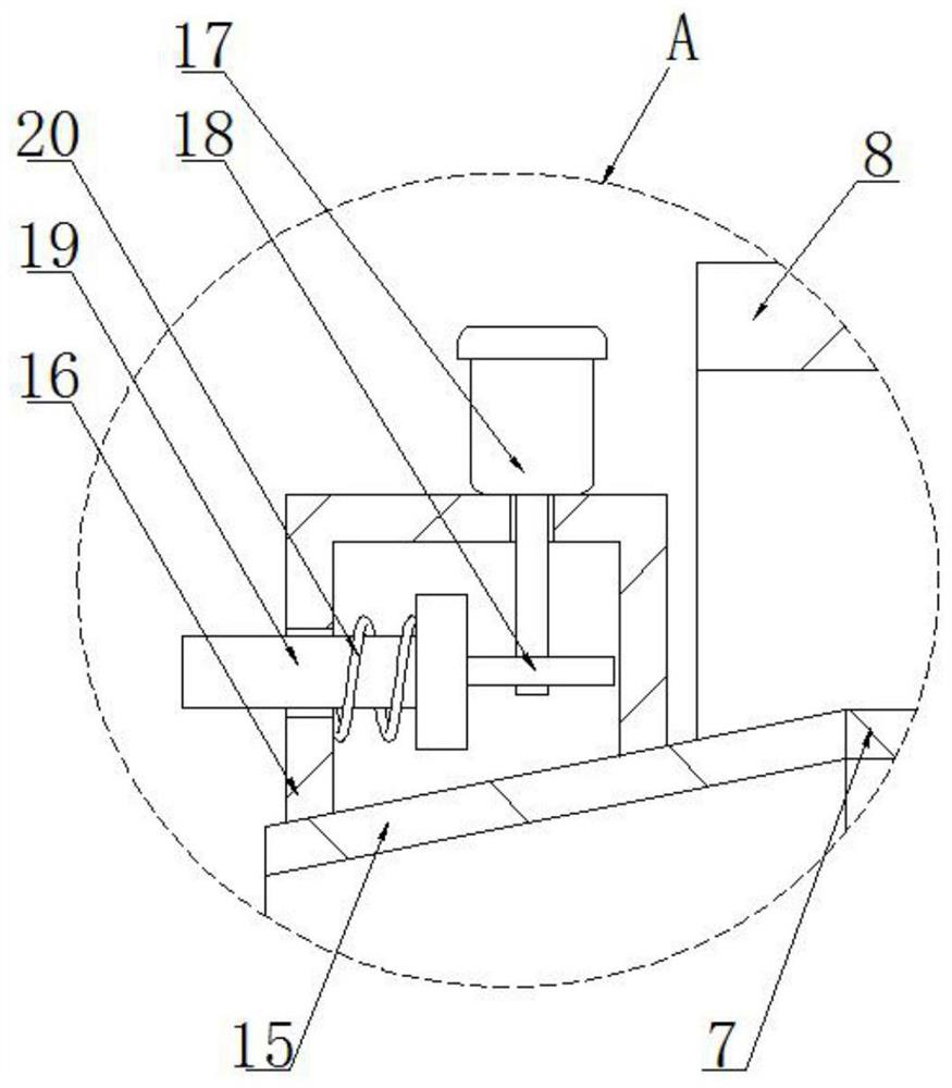
[0031] refer to image 3 , the vibration device includes a vibration housing 16 fixedly connected to the surface of the conical tube 15, the upper surface of the vibration housing 16 is fixedly connected with a vibration motor 17, the output end of the vibration motor 17 is fixedly connected with an eccentric wheel 18, the vibration housing 16 A through hole is opened on the side, and the inner wall of the through hole is slidably connected with a stepped columnar vibrating hammer 19, and the side of the vibrating hammer 19 overlaps the surface of the eccentric wheel 18, and the surface of the vibrating hammer 19 is covered with a spring 20. The spring 20 One end of the spring 20 is fixedly connected to the step surface of the vibration hammer 19, and the other end of the spring 20 is fixedly connected to the inner surface of the vibration housing 16.
[0032] In this embodiment, the activation of the vibrating motor 17 causes the eccentric wheel 18 to drive the vibrating hamm...
PUM
 Abstract
Description
Claims
Application Information
 - R&D
- Intellectual Property
- Life Sciences
- Materials
- Tech Scout
- Unparalleled Data Quality
- Higher Quality Content
- 60% Fewer Hallucinations
Browse by: Latest US Patents, China's latest patents, Technical Efficacy Thesaurus, Application Domain, Technology Topic, Popular Technical Reports.
© 2025 PatSnap. All rights reserved.Legal|Privacy policy|Modern Slavery Act Transparency Statement|Sitemap|About US| Contact US: help@patsnap.com


