
Device for increasing TIG welding speed

A technology of welding speed and welding wire, which is applied in the field of devices for improving TIG welding speed, can solve the problems of reducing welding speed, low welding wire conveying efficiency, unstable welding wire conveying speed, etc., and achieve the effect of improving conveying efficiency and welding speed

Inactive Publication Date: 2021-03-12
宿州市宝宏纺织有限公司
View PDF0 Cites 0 Cited by
  • Summary
  • Abstract
  • Description
  • Claims
  • Application Information

AI Technical Summary

Problems solved by technology

[0003] In the actual operation process of traditional TIG welding, the welding wire is manually conveyed, which is easy to cause unstable wire conveying speed, low wire conveying efficiency, and greatly reduces its welding speed. Therefore, it is necessary to design a method to increase the TIG welding speed. device

Method used


Image

  • Device for increasing TIG welding speed
  • Device for increasing TIG welding speed
  • Device for increasing TIG welding speed

Examples


Embodiment Construction

[0025] In order to make the technical means, creative features, goals and effects achieved by the present invention easy to understand, the present invention will be further described below in conjunction with specific embodiments.

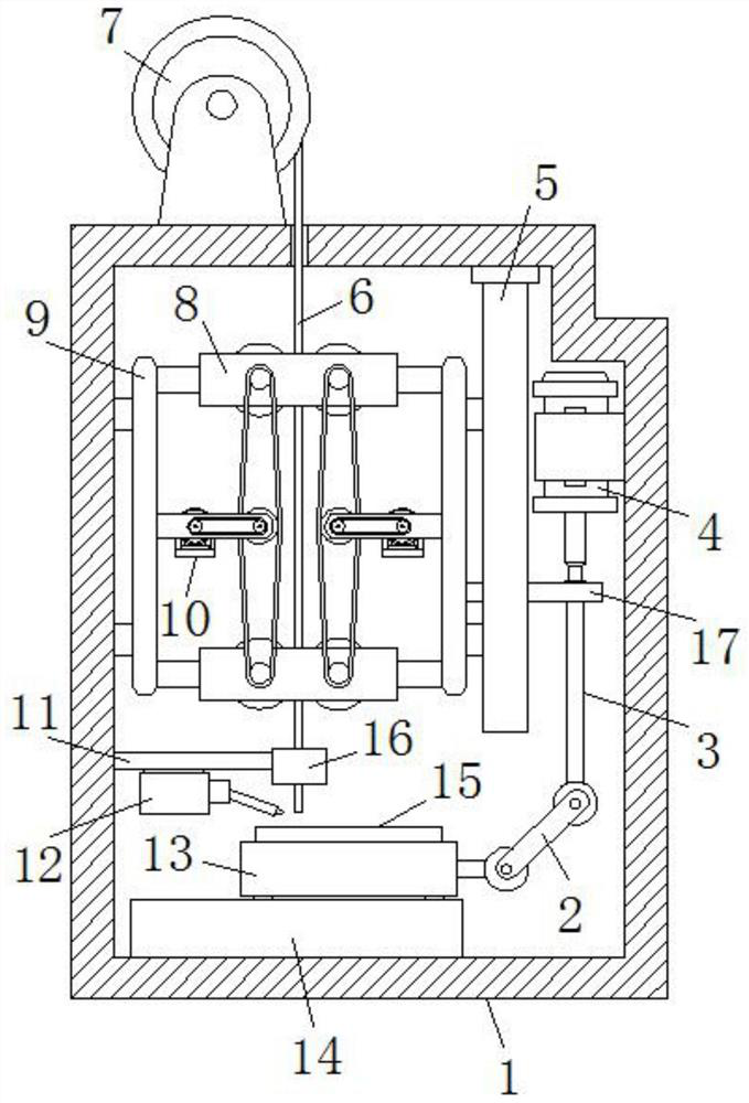
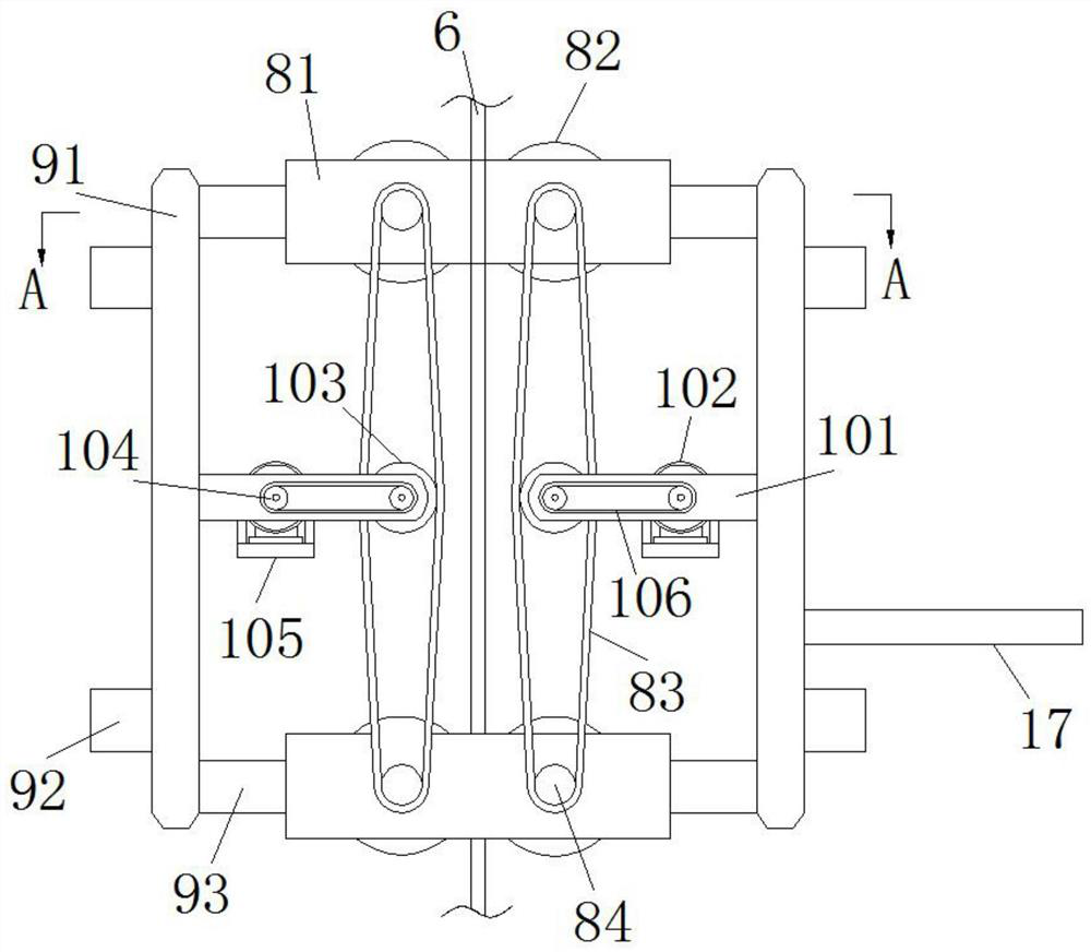
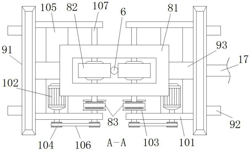
[0026] Such as Figure 1-Figure 7As shown, a device for improving TIG welding speed according to the present invention includes a protective box 1, a wire winding mechanism 7 is fixedly installed on the top of the protective box 1, and a welding wire 6 is wound on the wire winding mechanism 7. Inside the protective box 1 The limit plate 5 is fixedly installed on the top wall, and an elevating mechanism 9 is slidably installed on an inner wall of the protective box 1. An elevating mechanism 9 is slidably installed on the limit plate 5, and two elevating mechanisms 9 are arranged symmetrically. Two wire feeding mechanisms 8 are installed slidingly between the lifting mechanisms 9, a drive mechanism 10 is fixedly installed on the two lifting mechanis...


PUM


Abstract

The invention relates to the technical field of TIG welding, in particular to a device for increasing the TIG welding speed. The device comprises a protection box. A wire winding mechanism is fixedlyinstalled at the top end of the protection box. A welding wire is wound around the wire winding mechanism. A limiting plate is installed on the inner top wall of the protection box. A lifting mechanism is installed on one inner wall of the protection box in a sliding manner. A lifting mechanism is installed on the limiting plate in a sliding manner. Two wire feeding mechanisms are installed between the two lifting mechanisms in a sliding manner. The two lifting mechanisms are each fixedly provided with a driving mechanism. An air cylinder is fixedly installed on the inner wall of the protection box. An abutting plate is fixedly installed at the output end of the air cylinder. A sliding base is fixedly installed on the inner bottom wall of the protection box. A sliding table is installed atthe top end of the sliding base in a sliding manner. One end of a connecting rod mechanism is fixedly connected with the sliding table. A base material is clamped and placed at the top end of the sliding table. A wire guiding wheel is driven by a motor to rotate, then the welding wire is conveyed downwards, and compared with manual wire feeding, the wire feeding efficiency of the device can be improved, and the welding speed of the device can be effectively increased.

Description

technical field [0001] The invention relates to the technical field of TIG welding, in particular to a device for increasing the speed of TIG welding. Background technique [0002] TIG welding is tungsten inert gas welding, generally called non-melting electrode gas shielded welding. Pure tungsten or activated tungsten is used as an inert gas shielded arc welding that does not melt the electrode, and the arc between the tungsten electrode and the workpiece is used as a heat source to melt and add it. The welding wire is used to form the weld seam. During the welding process, the tungsten pole does not melt, and only acts as an electrode. At the same time, the nozzle of the welding torch is fed with argon or helium gas for protection, and additional metal can be added as needed. During the welding process, The welding wire is transported to the surface of the base metal, and it is welded by the welding torch to form a welding spot on the surface of the base metal. [0003] I...

Claims


Application Information

Patent Timeline
IPC IPC(8): B23K9/133B23K9/167B23K9/32
CPCB23K9/133B23K9/167B23K9/32
Inventor 赵纪明王鑫
Owner 宿州市宝宏纺织有限公司
Features
  • Generate Ideas
  • Intellectual Property
  • Life Sciences
  • Materials
  • Tech Scout
  • Unparalleled Data Quality
  • Higher Quality Content
  • 60% Fewer Hallucinations
Learn More