Non-resonant vibration auxiliary magneto-rheological polishing device and method for machining optical element

An optical element and polishing device technology, applied in the field of non-resonant vibration-assisted magnetorheological polishing devices, can solve the problems of low polishing efficiency and poor stability, and achieve increased tangential polishing force, large stroke displacement output, improved polishing efficiency and The effect of surface precision

Active Publication Date: 2021-03-12
CHANGCHUN UNIV OF TECH
View PDF17 Cites 2 Cited by
  • Summary
  • Abstract
  • Description
  • Claims
  • Application Information

AI Technical Summary

Problems solved by technology

[0005] The invention provides a non-resonant vibration-assisted magnetorheological polishing device and method for processing optical elements, so as to improve the problems of low polishing efficiency and poor stability of traditional magnetorheological polishing

Method used


Image

  • Non-resonant vibration auxiliary magneto-rheological polishing device and method for machining optical element
  • Non-resonant vibration auxiliary magneto-rheological polishing device and method for machining optical element
  • Non-resonant vibration auxiliary magneto-rheological polishing device and method for machining optical element

Examples


Embodiment Construction

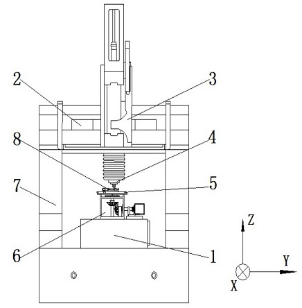
[0040] Such as figure 1 As shown, a non-resonant vibration-assisted magnetorheological polishing device for processing optical components includes an X-direction air bearing guide rail 1, a Y direction air bearing guide rail 2, a Z direction air bearing guide rail 3, a polishing cutter head moving platform 4, a vibration Device 5, magnet rotating table 6, machine frame 7 and optical element 8, X-direction air-floating guide rail 1 is installed on machine tool frame 7, Y-direction air-floating guide 2 is connected to machine tool frame 7 through screws, and Z-direction air-floating guide rail 3 passes through The screw is connected with the Y-direction air bearing guide rail 2, the polishing cutter head moving platform 4 is connected with the Z-direction air bearing guide rail 3 through screws, the vibration device 5 is connected with the magnet rotating table 6 through screws, and the magnet rotating table 6 is connected with the X-direction air bearing through screws The guid...


PUM

PropertyMeasurementUnit
surface roughnessaaaaaaaaaa

Abstract

The invention relates to a non-resonant vibration auxiliary magneto-rheological polishing device and method for machining an optical element, and belongs to the field of ultra-precision machining. AnX-direction air floatation guide rail and a Y-direction air floatation guide rail are installed on a machine tool frame and drive an element to move in the X-direction and the Y-direction; an Z-direction air floatation guide rail and the Y-direction air floatation guide rail are connected through screws, so that a polishing tool bit moving platform fixed at the bottom end of the Z-direction air floatation guide rail moves in the Z direction; a magnet rotating table is fixed to the machine tool frame, and a generated dynamic magnetic field enables magnetorheological fluid to be subjected to a magnetization reaction to form a magnetic cluster; and a vibration device is installed on the magnet rotating table and drives the element to vibrate in a two-dimensional mode. According to the non-resonant vibration auxiliary magneto-rheological polishing method provided by the invention,a rotary magnetic brush is combined with two-dimensional vibration, so that an abrasive material makes full contact with a surface microstructure of the element, the abrasive material effectively removes scratches, burrs and cracks on the surface of the element through composite motion of the rotary magnetic brush and the two-dimensional vibration, and the polishing efficiency is improved, and the shape precision of the element is better reserved.

Description

technical field [0001] The invention relates to the field of ultra-precision processing, in particular to a non-resonant vibration-assisted magnetorheological polishing device and method for processing optical elements. Background technique [0002] With the continuous advancement of science and technology, new optical components have the advantages of small size, light weight, and excellent optical performance. They are widely used in slide projectors, infrared detectors, film magnifiers, and aerospace. The surface shape accuracy and surface roughness of optical components directly affect the imaging quality and resolution, but some optical components processed by industrial processing methods cannot meet the requirements of use due to the inherent defects of the processing technology. The components are precision polished. For some optical components with complex microstructures, the traditional mechanical polishing technology cannot polish the microstructures on the optic...

Claims


Application Information

Patent Timeline
Patent Type & Authority Applications(China)
IPC IPC(8): B24B1/00B24B1/04
CPCB24B1/005B24B1/04Y02P70/10
Inventor 谷岩林洁琼卢发祥周伟东马连杰姜吉军付斌康洺硕刘骜孙恩刘拓含于丰源孙金鹏张森李鹏程
Owner CHANGCHUN UNIV OF TECH
Why Eureka
Try Eureka