Clothes hanger

A drying rack and arc technology, applied in the field of drying racks, can solve the problems of slow drying of clothes in the rear row, affecting the drying speed, and stacking of clothes, etc., and achieve the effects of good use experience, safe and reliable use, and good operability.

Inactive Publication Date: 2021-03-12
刘洋洋
View PDF1 Cites 1 Cited by
  • Summary
  • Abstract
  • Description
  • Claims
  • Application Information

AI Technical Summary

Problems solved by technology

[0006] Aiming at the deficiencies of the prior art, the present invention provides a clothes drying rack, which solves the problem that the clothes in the back row will be blocked by the clothes in the front row when the clot

Method used


Image

  • Clothes hanger
  • Clothes hanger
  • Clothes hanger

Examples


Embodiment 1

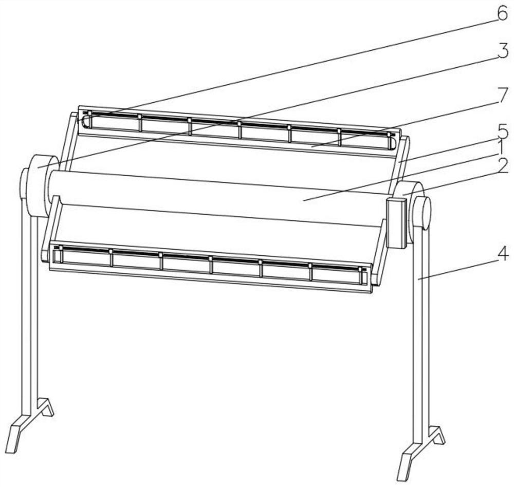
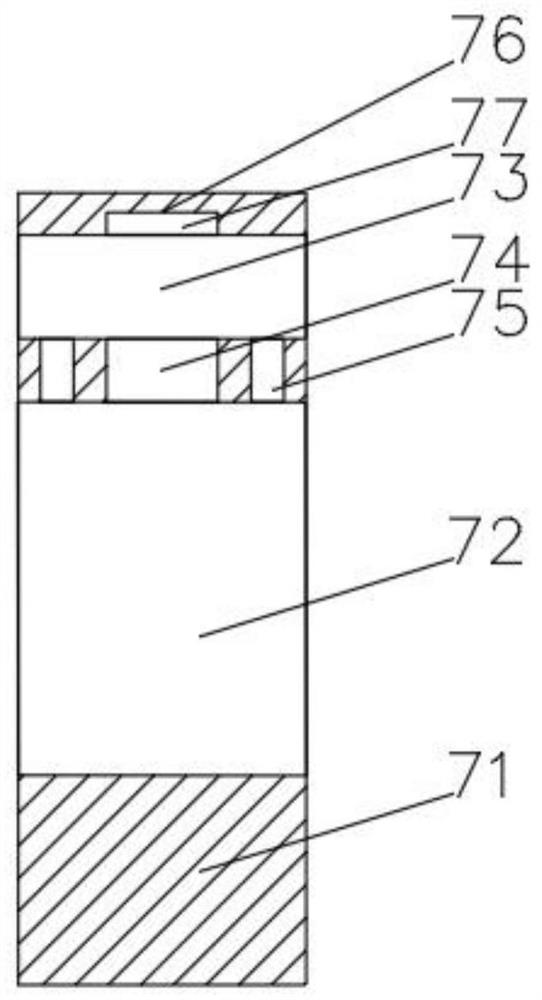
[0033] see Figure 1-3, the present invention provides a technical solution: a drying rack, including a rotating shaft 1, characterized in that: one end of the rotating shaft 1 is fixedly connected with a rotating device 2, and the end of the rotating shaft 1 away from the rotating device 2 penetrates and is connected with a fixed disk 3 through a bearing for rotation , the rotating device 2 and the bottom of the fixed disk 3 are fixedly connected with a bracket 4, the sides of the two ends of the rotating shaft 1 are fixedly connected with a support rod 5, and one side of the support rod 5 is connected with a rotating bolt 6 through a bearing for rotation, and the rotating bolt 6 is far away from the supporting rod 5 One end of one end is fixedly connected with a drying device 7, and the drying device 7 includes a drying rack 71, and one side of the drying rack 71 is provided with a hanging hole 72, and the part of the drying rack 71 side that is located above the hanging hole...

Embodiment 2

[0035] see Figure 1-5 On the basis of Embodiment 1, the present invention provides a technical solution: the rotating device 2 includes a rotating shell 21, the inner wall of the rotating shell 21 is connected to a rotating plate 22 through a rotating shaft, and an arc-shaped piston rod is fixedly connected to the edge of one side of the rotating plate 22. 23. One end of the arc-shaped piston rod 23 runs through and is slidably connected to an arc-shaped piston barrel 24. One end of the arc-shaped piston rod 23 located on the inner wall of the arc-shaped piston barrel 24 is fixedly connected to a piston head 25. The arc-shaped piston barrel 24 is far away from the arc-shaped piston rod. One end of 23 is communicated with outlet nozzle 26, and one side of rotating plate 22 is provided with draw-in groove 27, and the bottom of draw-in groove 27 inner wall is fixedly connected with jacking spring 28, and the end of jacking-up spring 28 away from draw-in groove 27 inner wall is fi...


PUM


Abstract

The invention discloses a clothes hanger. The clothes hanger comprises a rotating shaft; one end of the rotating shaft is fixedly connected with a rotating device; the end, away from the rotating device, of the rotating shaft penetrates through and is rotationally connected with a fixed disc through a bearing; supports are fixedly connected to the bottoms of the rotating device and the fixed disc;supporting rods are fixedly connected to the side faces of the two ends of the rotating shaft; rotating bolts are rotatably connected to one sides of the corresponding supporting rods through bearings; airing devices are fixedly connected to the ends, away from the supporting rods, of the rotating bolts; each airing device comprises an airing frame; a hanging hole is formed in one side of each airing frame; a sliding hole is formed in the portion, located above the hanging hole, of one side of each airing frame; and a sliding way is formed in the top of the inner wall of each hanging hole. The invention relates to the technical field of clothes hangers. The clothes hanger is relatively high in airing efficiency, good in operability and good in use experience, capable of avoiding clothes accumulation and insufficient airing of back-row clothes, relatively good in airing effect and safe and reliable to use.

Description

technical field [0001] The invention relates to the technical field of clothes drying racks, in particular to a clothes drying rack. Background technique [0002] Clothes hangers, as household items that people use every day, have become a daily necessities for many families. "Clothes hangers" are a major characteristic product in China. The industry has been formed for more than ten years, and the technology has been continuously improved and changed since its inception. . [0003] For example, as described in Chinese patent CN1696386A, it includes a plurality of bushing connectors, a plurality of elongated elements and a plurality of crossbars with end connectors. The sleeve connector includes a thickened head, a hollow body portion defining a central bore, and an end portion larger in diameter than the hollow body portion, the sleeve connector further defining a groove on the tail portion for allowing the end portion to be resilient The end portion is deflected inwardly...

Claims


Application Information

Patent Timeline
IPC IPC(8): D06F57/06
CPCD06F57/06
Inventor 申翱刘洋洋
Owner 刘洋洋
Why Eureka
Try Eureka