Water conservancy flood prevention plate

A water conservancy and roof technology, applied in water conservancy projects, embankments, dams, etc., can solve the problems of poor flood control effect, loss of flood control plate, overflow, etc.

Inactive Publication Date: 2021-03-12
伍强
View PDF1 Cites 2 Cited by
  • Summary
  • Abstract
  • Description
  • Claims
  • Application Information

AI Technical Summary

Problems solved by technology

[0006] Aiming at the deficiencies of the prior art, the present invention provides a water conservancy flood control board, which solves the problem that the currently used water conservancy flood control board is usually used as a water retaining board. When the underwater pressure is high, the pressure on the

Method used


Image

  • Water conservancy flood prevention plate
  • Water conservancy flood prevention plate
  • Water conservancy flood prevention plate

Examples


Embodiment 1

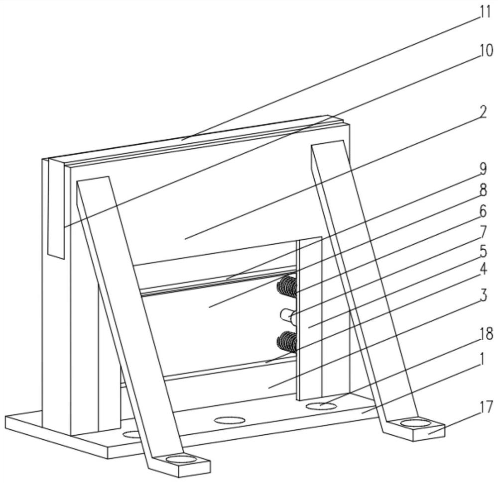
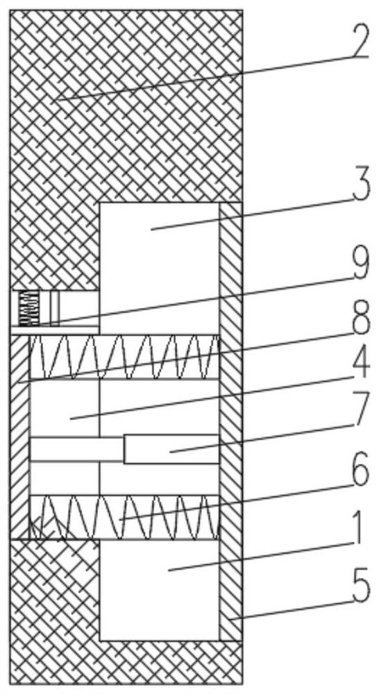
[0036] see Figure 1-4, the present invention provides a technical solution: a water conservancy flood control plate, including a fixed base 1, a flood control plate body 2 is fixedly connected to the top of the fixed base 1, a buffer tank 3 is opened on one side of the flood control plate body 2, and the bottom of the inner wall of the buffer tank 3 is opened There is a buffer hole 4, and both sides of the end of the buffer groove 3 away from the buffer hole 4 are fixedly connected with a support plate 5, and both ends of the side of the support plate 5 close to the buffer hole 4 are fixedly connected with a buffer spring 6, and the support plate 5 is close to the buffer. The central position of one side of the hole 4 is fixedly connected with a telescopic rod 7, the end of the buffer spring 6 away from the support plate 5 is fixedly connected with a buffer plate 8, the end of the telescopic rod 7 away from the support plate 5 is fixedly connected with the buffer plate 8, and ...

Embodiment 2

[0038] see Figure 1-6 On the basis of Embodiment 1, the present invention provides a technical solution: a water conservancy flood control plate, including a fixed base 1, characterized in that: the top of the fixed base 1 is fixedly connected with a flood control plate body 2, and the top of the flood control plate body 2 is provided with The chute 10, the inner wall of the chute 10 is slidably connected with an auxiliary baffle 11, the bottom of the auxiliary baffle 11 is fixedly connected with a buckle device 12, and the bottom of the inner wall of the chute 10 is provided with a slide hole 13 at a position below the buckle device 12, and the slide hole Both sides of the inner wall of 13 are provided with buckle grooves 14, and both ends of the bottom of the auxiliary baffle 11 are fixedly connected with auxiliary springs 15. Including the first buckle bar 121, both sides of one end of the first buckle bar 121 are fixedly connected with rollers 122, and the side of the rol...


PUM


Abstract

The invention discloses a water conservancy flood prevention plate. The water conservancy flood prevention plate comprises a fixed base, wherein the top of the fixed base is fixedly connected with a flood prevention plate body; a buffer groove is formed in one side of the flood prevention plate body; a buffer hole is formed in the bottom of the inner wall of the buffer groove; the two sides of theend, far away from the buffer hole, of the inner wall of the buffer groove are fixedly connected with supporting plates; the two ends of the side, close to the buffer hole, of each supporting plate are fixedly connected with buffer springs; the center of the side, close to the buffer hole, of each supporting plate is fixedly connected with a telescopic rod; the ends, far away from the supportingplates, of the buffer springs are fixedly connected with buffer plates; the ends, far away from the supporting plates, of the telescopic rods are fixedly connected with the buffer plates; and the bottom of the inner wall of the buffer hole is fixedly connected with a buffer sealing device. The invention relates to the technical field of water conservancy projects. The water conservancy flood prevention plate can effectively reduce the impact force of water flow, and is good in buffer effect, high in flood resistance, not prone to toppling, large in water retaining capacity and convenient to carry.

Description

technical field [0001] The invention relates to the technical field of water conservancy engineering, in particular to a water conservancy flood control board. Background technique [0002] Water conservancy projects are projects built to control and allocate natural surface water and groundwater to achieve the purpose of eliminating harm and rejuvenating profits, also known as water projects. [0003] For example, as described in Chinese patent CN111608135A, it includes a flood control baffle, a lifting and lowering flood control baffle is installed in the middle of the flood control baffle, and a rubber pad is arranged between the lifting and lowering flood control baffle and the flood control baffle, and the lifting and lowering flood control baffle The front end of the buoyancy plate is fixedly installed, and both sides of the lifting and flood prevention protection plate are provided with lifting chute, the inner side of the lifting chute is equipped with a connecting s...

Claims


Application Information

Patent Timeline
IPC IPC(8): E02B3/10
CPCE02B3/106Y02A10/11
Inventor 伍强
Owner 伍强
Why Eureka
Try Eureka