Servo quick pressure cylinder

A supercharged cylinder, fast technology, applied in the direction of fluid pressure converter, fluid pressure actuating device, belt/chain/gear, etc., can solve the problems of high failure rate, not very accurate positioning, affecting production, etc., to reduce Use requirements, accurate positioning effect

Pending Publication Date: 2021-03-12
罗长云
View PDF0 Cites 0 Cited by
  • Summary
  • Abstract
  • Description
  • Claims
  • Application Information

AI Technical Summary

Problems solved by technology

[0003] At present, the existing booster cylinder is improved by combining the advantages of the air cylinder and the oil cylinder, so the requirements for use are relatively high, and the positioning of the existing booster cylinder is not very accurate during operation, and failure The high efficiency will seriously affect the subsequent production. Therefore, it is urgent to improve the existing booster cylinder

Method used


Image

  • Servo quick pressure cylinder
  • Servo quick pressure cylinder
  • Servo quick pressure cylinder

Examples


Embodiment 1

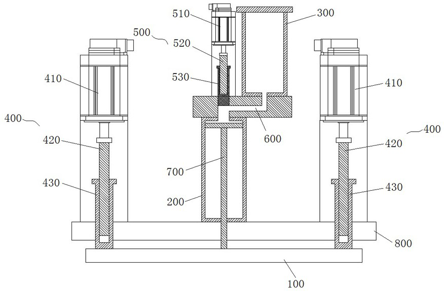
[0025] see figure 1 and figure 2 , a servo fast booster cylinder, including a connecting plate 100, a booster cylinder 200, an oil barrel 300, a first drive assembly 400 and a second drive assembly 500, the second drive assembly 500 is arranged on the booster cylinder 200 top, the bottom side of the oil barrel 300 is connected to the top side of the pressurized cylinder 200 to form an oil channel 600, the pressurized cylinder 200 is provided with a piston rod 700, and one end of the piston rod 700 increases The outer extension of the cylinder body 200 is connected to the middle of the connecting plate 100 , and the two ends of the connecting plate 100 are respectively connected with the first driving assembly 400 .

[0026] In this embodiment, the first drive assembly 400 includes a first servo motor 410, a first screw 420 and a main shaft 430, one end of the first screw 420 is connected to the first servo motor 410, and the other end is covered with It is installed in the ...

Embodiment 2

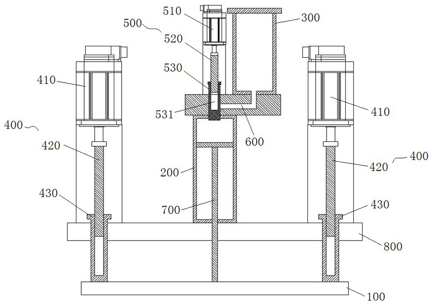
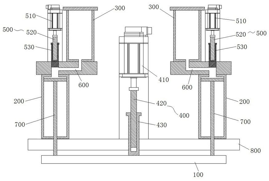
[0032] see image 3 and Figure 4 , the servo fast booster cylinder includes a connection plate 100, a booster cylinder 200, an oil barrel 300, a first drive assembly 400 and a second drive assembly 500, and the booster cylinder 200, the oil barrel 300 and the second drive There are two sets of assemblies 500 respectively, the second drive assembly 500 is arranged on the top of the pressurized cylinder 200, the bottom side of the oil barrel 300 is connected to the top side of the pressurized cylinder 200, and forms an oil channel 600, Piston rods 700 are arranged in the two groups of pressurized cylinders 200, and one end of the two groups of piston rods 700 extends to the outside of the pressurized cylinders 200, and is respectively connected to both ends of the connecting plate 100, and the ends of the connecting plate 100 The middle part is connected with a first driving assembly 400 .

[0033] The structure of the pressurized cylinder in this embodiment is basically the ...

Embodiment 3

[0035] see Figure 5 and Figure 6 , the servo fast booster cylinder includes a booster cylinder 200, an oil barrel 300, a first drive assembly 400 and a second drive assembly 500, the bottom side of the oil barrel 300 is connected to the top side of the booster cylinder 200, And form an oil channel 600, the second drive assembly 500 is connected to the oil channel 600, the inside of the pressurized cylinder 200 is provided with a piston rod 700, and the two ends of the piston rod 700 are respectively connected to the pressurized cylinder 200 The outside extends, and one end thereof is provided with a piston rod counterbore 710 , and the first drive assembly 400 is connected to one end of the piston rod 700 provided with the piston rod counterbore 710 .

[0036] In this embodiment, the first drive assembly 400 includes a first servo motor 410 and a first screw rod 420, one end of the first screw rod 420 is connected to the first servo motor 410, and the other end is inserted ...


PUM


Abstract

The invention discloses a servo quick pressure cylinder comprising a connecting plate, a pressure cylinder block, an oil drum, first driving assemblies and a second driving assembly. The second driving assembly is arranged on the top of the pressure cylinder block, and the side face of the bottom of the oil drum is connected with the side face of the top of the pressure cylinder block to form an oil channel; and a piston rod is arranged in the pressure cylinder block; and one end of the piston rod extends out of the pressure cylinder block, and is connected with the middle of the connecting plate, and the two ends of the connecting plate are connected with first driving assemblies separately. According to the servo quick pressure cylinder, the first driving assemblies and the second driving assembly are used as mechanical transmission force, and in combination with oil pressure, the servo quick pressure cylinder is accurately located during pressurizing; and meanwhile, the servo quickpressure cylinder can adapt to more severe occasions, so that the use requirement of the servo quick pressure cylinder is reduced.

Description

technical field [0001] The invention relates to the technical field of supercharging equipment, in particular to a servo fast supercharging cylinder. Background technique [0002] The booster cylinder is also called the gas-liquid booster cylinder. The booster cylinder is an improved design combining the advantages of the air cylinder and the oil cylinder. The hydraulic oil is strictly isolated from the compressed air. The piston rod in the cylinder will automatically start when it touches the work piece. It is more stable than pneumatic transmission, the cylinder device is simple, and the output is easy to adjust. Under the same conditions, the high output of the hydraulic machine can be achieved, the energy consumption is low, and the soft landing does not damage the mold. It is easy to install and the special booster cylinder can be installed at any angle of 360 degrees. Small space, few failures, no temperature rise, long life, low noise, and other core features. [000...

Claims


Application Information

Patent Timeline
Patent Type & Authority Applications(China)
IPC IPC(8): F15B3/00F15B15/14F16H25/20
CPCF15B3/00F15B15/14F15B2015/1495F16H25/20F16H2025/2075
Inventor 罗长云
Owner 罗长云
Why Eureka
Try Eureka