Plate levelness detection device for mechanical manufacturing

A technology of mechanical manufacturing and detection device, applied in the field of plate levelness detection device, can solve problems such as troublesome operation process, and achieve the effect of avoiding instability

Inactive Publication Date: 2021-03-12
李济存
View PDF0 Cites 0 Cited by
  • Summary
  • Abstract
  • Description
  • Claims
  • Application Information

AI Technical Summary

Problems solved by technology

[0003] At present, when the existing levelness detection device for the plate used in mechanical manufacturing is used, it usually needs to be fixed by external electric components, which makes the operation process more troublesome. Therefore, it is urgent to design a plate for mechanical manufacturing Component level detection device to solve the above problems

Method used


Image

  • Plate levelness detection device for mechanical manufacturing
  • Plate levelness detection device for mechanical manufacturing
  • Plate levelness detection device for mechanical manufacturing

Examples


Embodiment 1

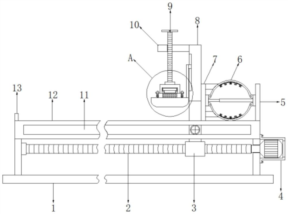
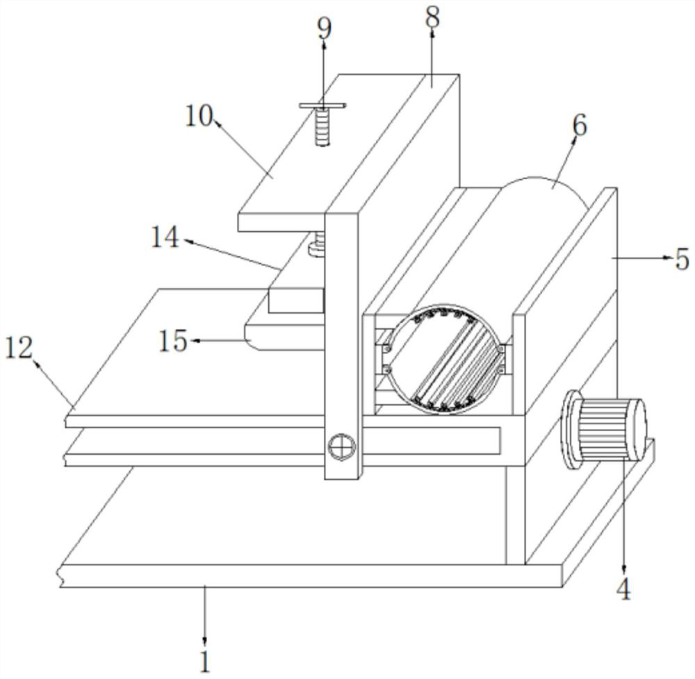
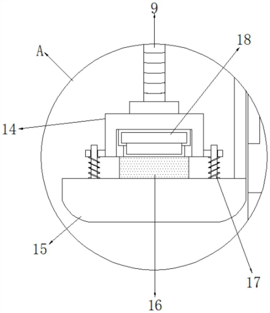
[0031] refer to Figure 1-5 , a plate levelness detection device for mechanical manufacturing, comprising a support platform 12, the outer wall of the support platform 12 is sleeved with a movable plate 8, and a top plate 10 is welded on the top of one side of the movable plate 8, and the top of the top plate 10 is There is a threaded hole on the side, and the inner wall of the threaded hole is threadedly connected with a threaded rod 9. The bottom of the threaded rod 9 is set as a detection mechanism. Plate 13, a clamping plate 7 is placed on one side of the top of the support platform 12, and a side of the clamping plate 7 and a side of the fixed plate 5 are welded with a connecting seat 19, and a side top of the connecting seat 19 and a U-shaped seats 20 are welded between the side bottoms, and steel sheets 6 are connected between the inner walls on both sides of the corresponding U-shaped seats 20 through pin shaft rotation, and rubber pads are welded in the middle of the ...

Embodiment 2

[0041] refer to Image 6 , a plate levelness detection device for mechanical manufacturing. Compared with Embodiment 1, this embodiment replaces the forward and reverse motor 4 and the threaded screw 2 with a hydraulic cylinder 28 and a connecting rod 29, and the hydraulic cylinder 28 It is connected to one side of the support plate by bolts, and the connecting rod 29 is connected between the piston end of the hydraulic cylinder 28 and one side of the movable sleeve 3 by bolts.

[0042] Working principle: Connect the hydraulic cylinder 28 to the hydraulic system, directly use the hydraulic cylinder 28 to adjust the position of the connecting rod 29 and the movable sleeve 3, so that the movable plate 8 moves on the support table 12, replacing the forward and reverse motor 4 and the threaded screw 2 Displacement operation, to avoid the impact of vibration generated when the forward and reverse motor 4 is working, and to maintain the stability of the movement of the movable plate...


PUM


Abstract

The invention discloses a plate levelness detection device for mechanical manufacturing, and the device comprises a supporting platform, the outer wall of the supporting platform is sleeved with a movable plate, the top of one side of the movable plate is fixedly connected with a top plate, one side of the top of the top plate is provided with a threaded hole, the inner wall of the threaded hole is provided with a threaded rod, and the bottom of the threaded rod is provided with a detection mechanism. A fixing plate is fixedly connected to one end of the top of the supporting table, an abutting plate is fixedly connected to the other end of the top of the supporting table, a clamping plate is placed at one side of the top of the supporting table, and connecting bases are fixedly connectedto one side of the clamping plate and one side of the fixing plate. Whether the pressure of a pressure gauge is changed or not is observed, the levelness of a plate can be conveniently detected, the distance between the clamping plate and the fixing plate is increased through the steel sheet, the plate can be conveniently fixed, the deformation strength of the steel sheet is rapidly stabilized through a magnet strip, and the plate is rapidly clamped and fixed.

Description

technical field [0001] The invention relates to the technical field of mechanical manufacturing, in particular to a plate level detection device for mechanical manufacturing. Background technique [0002] Machinery manufacturing refers to the industrial sector engaged in the production of various power machinery, lifting and transportation machinery, chemical machinery, textile machinery, machine tools, tools, instruments, meters and other mechanical equipment. Machinery products refer to the products provided by machinery manufacturers to users or the market. Finished products or accessories such as automobiles, engines, machine tools, etc. are called mechanical products. For some mechanical parts, such as plates, they need to be tested for levelness during production. [0003] At present, when the existing levelness detection device for the plate used in mechanical manufacturing is used, it usually needs to be fixed by external electric components, which makes the operatio...

Claims


Application Information

Patent Timeline
Patent Type & Authority Applications(China)
IPC IPC(8): G01B21/30
CPCG01B21/30
Inventor 李济存
Owner 李济存
Why Eureka
Try Eureka