
Electromagnetic wire wrapping device

An electromagnetic wire and wrapping technology, which is applied in the manufacture of circuits, electrical components, cables/conductors, etc., can solve problems such as the inability to wrap more than three layers, improve wrapping efficiency, reduce equipment investment, and ensure order sexual effect

Inactive Publication Date: 2021-03-12
江西九星铜业有限公司
View PDF1 Cites 1 Cited by
  • Summary
  • Abstract
  • Description
  • Claims
  • Application Information

AI Technical Summary

Problems solved by technology

Although this solution achieves the purpose of multi-layer wrapping in one wrapping cage, since there are only two paper trays, it is impossible to wrap more than three layers, and reverse wrapping is often required in actual production , at this time still need multiple wrapping machines

Method used


Image

  • Electromagnetic wire wrapping device
  • Electromagnetic wire wrapping device
  • Electromagnetic wire wrapping device

Examples


Embodiment 1

[0052] Embodiment 1: as Image 6 Each briquetting block 604 on the crawler tractor 6 is controlled by a pneumatic device respectively, and a number of pressure rollers are arranged at the bottom of each briquetting block 604, and the pneumatic device can be used to press the briquetting block 604 tightly on the crawler belt 603 to generate sufficient friction force, and the adjacent pressing blocks 604 are movably connected by connecting rods 605, so that each pressing block 604 is driven by the pneumatic device to maintain consistency as much as possible.

Embodiment 2

[0053] Embodiment 2: as Figure 7 , the inner side of the track 603 is provided with cogs, the roller 602 and the briquetting block 604 are gears meshed with the cogging, the roller 602 and the briquetting block 604 are driven by the motor to rotate, and the roller 602 on the upper side and the briquetting block 604 are fixed On the back plate 606, the back plate 606 is controlled by a pneumatic device to lift up and down, so that the upper and lower crawlers 603 fit together; the crawler belt 603 directly relies on the cogging drive on the inner side, which can avoid slipping between the crawler belt 603 and the roller 602, ensuring that the crawler belt 603 driving force.

[0054] In order to facilitate speed regulation and realize stepless speed change, both the first motor 4 and the second motor 504 are variable frequency motors.

[0055] The first straightening assembly 1 includes several sets of straightening rollers arranged vertically and staggeredly to ensure that th...


PUM


Abstract

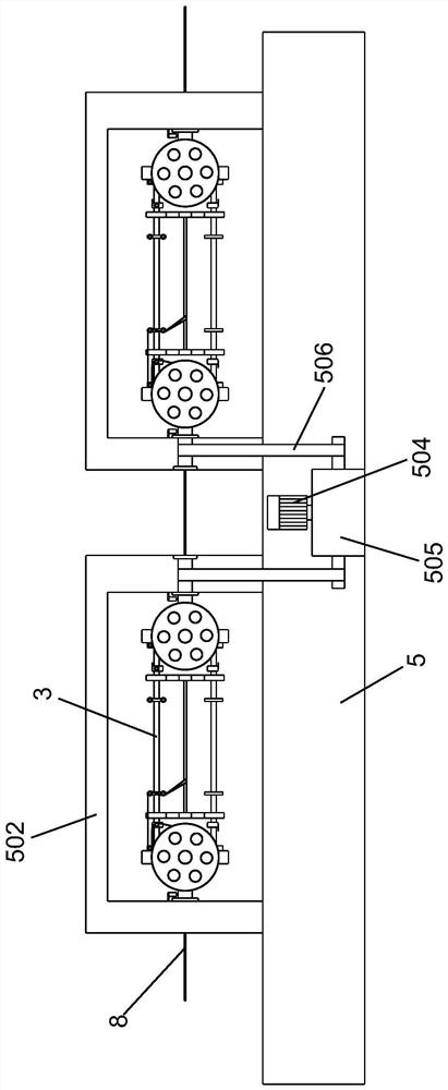
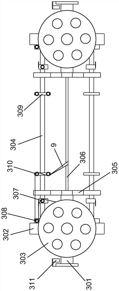
The invention provides an electromagnetic wire wrapping device which sequentially comprises a first straightening assembly, a wrapping machine frame, a wrapping machine table and a crawler-type traction machine, a plurality of wrapping frames are vertically distributed in the wrapping machine frame and driven by a first motor to rotate synchronously, and a second straightening assembly and two wrapping frames are sequentially and horizontally distributed on the wrapping machine table. A second motor and a clutch gearbox are arranged in the wrapping machine table, and output shafts are arrangedat the two ends of the clutch gearbox and connected with the hollow shafts of the two wrapping frames through tooth-shaped chains respectively; and the first motor, the second motor, the clutch gearbox, the rotating speed sensor and the self-reset switch are all electrically connected with the controller. The four paper discs can be placed on the single wrapping frame at the same time for wrapping, the wrapping efficiency is greatly improved, multi-layer wrapping can be achieved without multiple devices, the occupied area and the device investment are effectively reduced, and the production cost is reduced; and the two wrapping frames on the wrapping machine table can rotate reversely, so that wrapping in different rotating directions is realized, and different requirements of customers can be met.

Description

technical field [0001] The invention relates to the field of electromagnetic wire production, in particular to an electromagnetic wire wrapping device. Background technique [0002] Electromagnetic wire, also known as winding wire, is an insulated wire used to manufacture coils or windings in electrical products. Paper-covered wire is an extremely important type of electromagnetic wire. It is made of oxygen-free copper rod or electrical aluminum rod after being extruded or drawn and annealed by a mold of a certain specification. Winding wires made of materials (mainly cable paper, non-woven fabric, inter-turn insulating paper, mica tape, etc.). Compared with other wire materials, paper covered wire has many advantages, not only high flame retardancy, high reliability, but also wear and corrosion resistance, light weight and lower cost. Mainly used for winding coils of oil-immersed transformers, electric welding machines, electromagnets, etc. [0003] In the production pro...

Claims


Application Information

Patent Timeline
IPC IPC(8): H01B13/10H01B13/00
CPCH01B13/0036H01B13/10
Inventor 王浩臣黄细耿永怀康艳华
Owner 江西九星铜业有限公司
Learn More