
Magnetic regulation and control wire stripping device for communication cable

A communication cable and wire stripping device technology, which is applied in the direction of circuits, electrical components, recycling technology, etc., can solve the problems of low flexibility, inconvenient operation, etc., and achieve the effects of reducing wear, convenient operation, and convenient stripping operation

Inactive Publication Date: 2021-03-12
王成艳
View PDF0 Cites 2 Cited by
  • Summary
  • Abstract
  • Description
  • Claims
  • Application Information

AI Technical Summary

Problems solved by technology

[0005] The purpose of the present invention is to provide a magnetically controlled stripping device for communication cables that is easy to adjust and highly flexible for the above-mentioned problems of inconvenient operation and low flexibility

Method used


Image

  • Magnetic regulation and control wire stripping device for communication cable
  • Magnetic regulation and control wire stripping device for communication cable

Examples


Embodiment 1

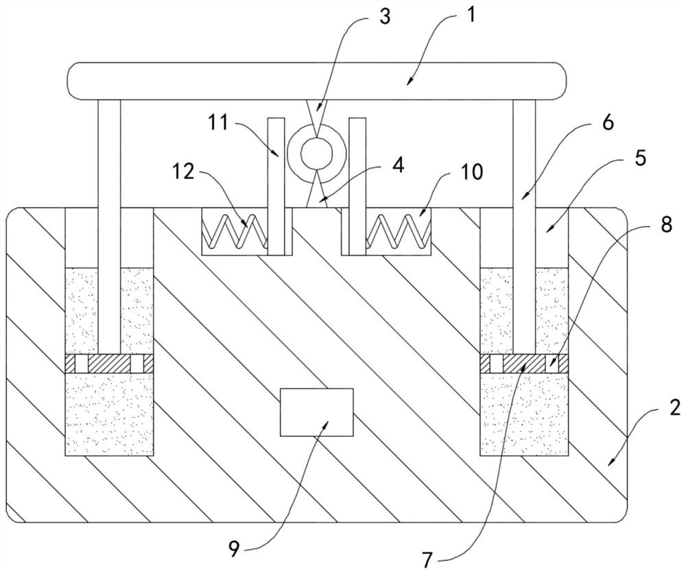
[0020] Such as figure 1 As shown, a magnetically controlled stripping device for communication cables includes an upper base 1 and a lower base 2, the upper base 1 and the lower base 2 are respectively equipped with a facing upper cutter 3 and a lower cutter 4, and the lower base 2 There are two chutes 5 on the upper surface, and the chutes 5 are filled with magnetorheological fluid, which is a mixture of tiny soft magnetic particles with high magnetic permeability and low magnetic hysteresis and non-magnetic permeable liquid. Suspension, the lower surface of the upper substrate 1 is fixedly connected with two sliding rods 6 matching the chute 5, and the lower end of the sliding rods 6 is fixedly connected with a lifting plate 7, and a plurality of guide holes 8 are arranged in the lifting plate 7, and the lifting The plate 7 is slidingly connected to the side wall of the chute 5, and the lower base 2 is provided with a storage battery 9, and the two ends of the storage batter...

Embodiment 2

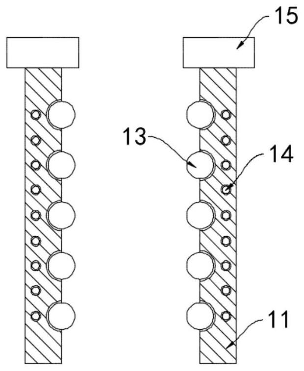
[0025] Such as figure 2 As shown, the difference between this embodiment and Embodiment 1 is that a plurality of balls 13 are embedded on the opposite side walls of the two limiting plates 11, the balls 13 are made of permanent magnets, and the limiting plates 11 are embedded with The closed coil 14 is helically wound and the winding direction is perpendicular to the rolling direction of the ball 13 . An electromagnet 15 is installed on the upper end of the limit plate 11 , and the electromagnet 15 is coupled to both ends of the closed coil 14 .

[0026] In this embodiment, when the communication cable slides between the two limiting plates 11, the balls 13 can roll freely on the limiting plates 11, reducing the wear on the surface of the communication cable and the limiting plates 11, and the communication cable during stripping. The ball 13 is driven to roll, and the closed coil 14 continuously cuts the magnetic lines of the ball 13 to generate an induced current, which sup...


PUM


Abstract

The invention belongs to the technical field of communication devices, and particularly relates to a magnetic regulation and control wire stripping device for a communication cable. The device comprises an upper base body and a lower base body, an upper cutter and a lower cutter which are opposite to each other are respectively mounted on the upper base body and the lower base body, and two sliding grooves are formed in the upper surface of the lower base body; magnetorheological fluid is filled in the sliding grooves, two sliding rods matched with the sliding grooves are fixedly connected tothe lower surface of the upper base body, and a lifting plate is fixedly connected to the lower ends of the sliding rods. A plurality of flow guide holes are formed in the lifting plate, the lifting plate is connected with the side walls of the sliding grooves in a sliding manner, and a storage battery is arranged in the lower base body. The two ends of the storage battery are electrically connected with the upper cutter and the lower cutter through the magnetorheological fluid in the two sliding grooves correspondingly. Through the principle that the fluidity of the magnetorheological fluid is reduced after the magnetorheological fluid is powered on, the upper cutter and the lower cutter are positioned to just make contact with a conductive core of the communication cable, an insulating skin is completely cut open, and the conductive core cannot be damaged, so that wire stripping operation can be conveniently, safely and effectively carried out.

Description

technical field [0001] The invention belongs to the technical field of communication equipment, in particular to a magnetically controlled stripping device for communication cables. Background technique [0002] Communication cables are cables used for telephone calls, fax documents, computer data and other electrical signals. They are composed of conductive cores and insulating skins. In order to save resources and reduce environmental pollution, communication cables after long-term use need to be recycled and reused. , so it is necessary to separate the insulating skin and conductive core of the communication cable through a stripping device. [0003] There are two kinds of traditional wire stripping devices, one is to strip wires through wire strippers, this method is complicated to operate, and the efficiency is not high, time-consuming and laborious; the other is to use wire strippers to strip wires, and the existing When the wire stripping machine strips communication...

Claims


Application Information

Patent Timeline
Patent Type & Authority Applications(China)
IPC IPC(8): H01B15/00
CPCH01B15/00H01B15/006Y02W30/82
Inventor 王成艳徐勇
Owner 王成艳
Learn More