Following hanging bracket

A hanger and frame beam technology, applied in the field of follower hangers, can solve problems such as no seat following hanger or displacement machine, inability to adjust width, and heavy burden on rehabilitation therapists or other service providers.

Active Publication Date: 2021-03-16
HANGZHOU ROBOCT TECH DEV CO LTD
View PDF8 Cites 1 Cited by
  • Summary
  • Abstract
  • Description
  • Claims
  • Application Information

AI Technical Summary

Problems solved by technology

Moreover, once the rehabilitation training time is long, the rehabilitation therapist or other service providers will have a heavy burden and cannot do other things during this period
[0004] In the above situation, once the user is unable to walk or needs to rest, in the prior art, there is no following hanger or displacement machine specially equipped with a seat.
[0005] At the same time, there are similar hangers in the prior art, such as the Chinese invention patent CN101791255B, the patent name is: walking aid exoskeleton robot system and control method, this patent discloses that there are "movable flat plate, integral support, lifting center of gravity adjustment system , an exoskeleton mechanical leg and a control system” is a vertical lower limb rehabilitation training robot. The mechanical leg hip joint adjustment device disclosed by the robot includes a width adjustment rack, a width adjustment shaft, a width adjustment gear, a width adjustment guide rail, a width adjustment The slider and the width adjustment handle, on the one hand, the width adjustment device is manually adjusted, which is not easy to operate. On the other hand, the width adjustment device only realizes the adjustment of the width, and does not realize the longitudinal fluctuation adjustment of the user during walking. Because according to the general gait, the hip joints on both sides of a person have wave-like ups and downs during walking, with

Method used


Image

  • Following hanging bracket
  • Following hanging bracket
  • Following hanging bracket

Examples


Embodiment approach

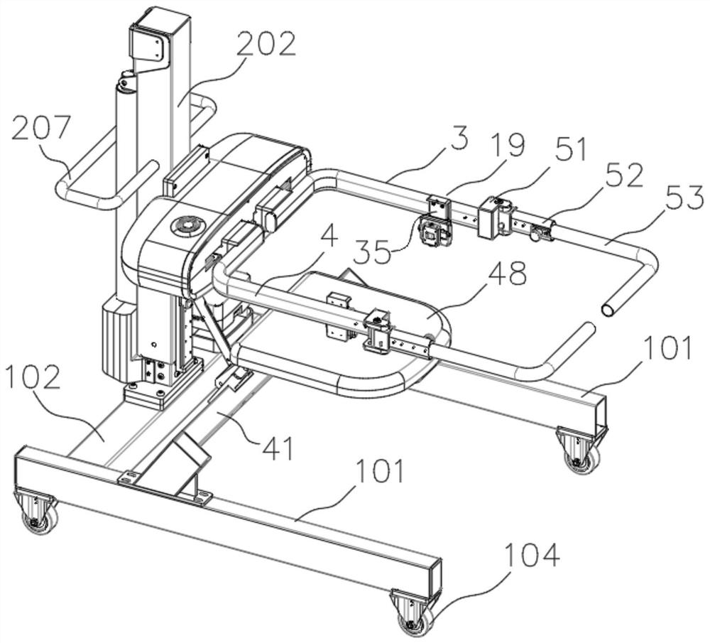
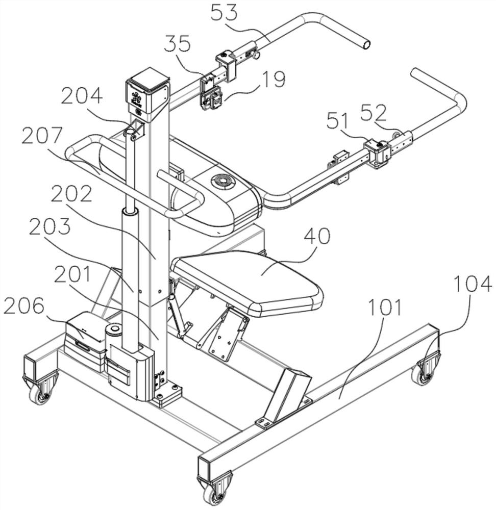
[0137] 1. One or 2 slides are mounted above or below the first slide and the second slide, the slide rail across the first slide and the second slider above or below. In this way, the slider is 2 when the slide slide is disposed between the slide rail and the second slide and the slide, so that when the slide is mounted, the slider is 2, and when the slide is installed, the slider is 4.

[0138] It should be noted that between the slider is fixed between the first skateboard or the second slide, fixed by bolt or welding.

[0139] The slider is fixed to the skateboard, the rail is fixed to the fixed plate, and the fixing plate is fixed to the column to form a certain fixed effect.

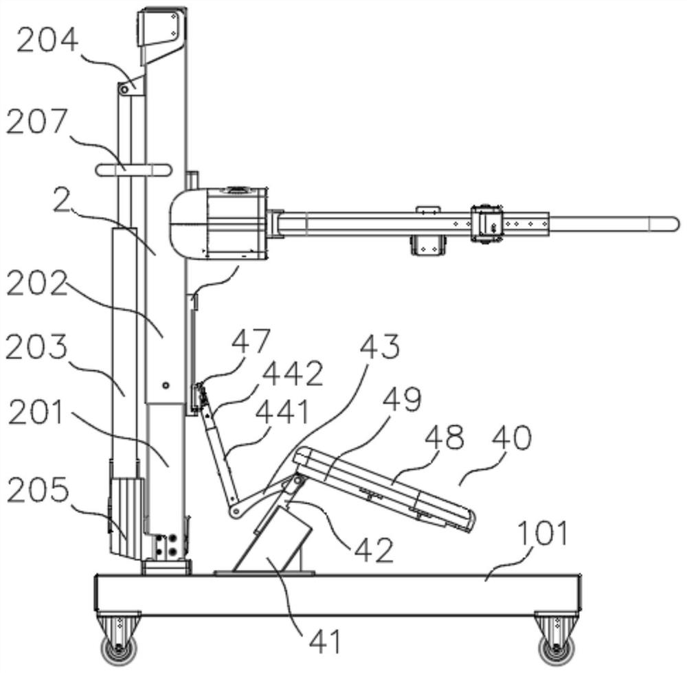
[0140] Synchronous adjustment method:

[0141] The first rack located above or below the first slide and the second rack of the first rack or above the second slider, the first rack and the second rack in the inner end and the same gear Meshing, the gear is fixed by the gear shaft with the column, and t...


PUM


Abstract

The invention provides a following hanging bracket. The following hanging bracket comprises a chassis, a stand column arranged on the chassis and an annular force arm arranged on the stand column andused for being connected with an exoskeleton robot, wherein the annular force arm is connected with a synchronous adjusting device; the chassis comprises a bearing beam and a frame beam, the stand column is arranged on the bearing beam, and a caster set is arranged below the frame beam; the annular force arm comprises a left force arm body and a right force arm body. Connecting pieces connected with the exoskeleton robot are arranged at the ends of the left force arm body and the right force arm body; the stand column comprises an inner stand column body and an outer stand column body, and thehanging bracket is provided with a folding stool. According to the folding stool, a user can have a rest and sit down at any time, the user can have a more scientific gait in the rehabilitation training process through a longitudinal sliding adjusting part and the universal adjusting connecting pieces, and the activity space of the hip in the walking state and the front-back and up-down adjustingfunctions of the hip in the walking process are guaranteed.

Description

Technical field [0001] The present invention relates to the field of mechanical, and Background technique [0002] The outer bone robot is a robot for rehabilitation or walking of the lower extremity. The user's weight and the weight of the outer bone robot are heavy, and the user will cause a heavy burden on the user. At this time, the bracket is required to carry out the user and the outer bone robot. Improve weight loss, reducing the user's burden, and has great improvement to walking state, user heart rate, muscle burden or sputum phenomenon. [0003] In addition, the user still requires a rehabilitation therapist or other servers following it after wearing an external bone robot, so as not to fall or other emergency situations when the user is unable to walk or other accidents. Moreover, once the rehabilitation is long, the rehabilitation therapist or other servers have a heavy burden and cannot be engaged in other matters during this period. [0004] In the above, once the ...

Claims


Application Information

Patent Timeline
IPC IPC(8): A61H3/04
CPCA61H3/04A61H2003/046A61H2003/007A61H2201/1207Y02A50/30
Inventor 王天
Owner HANGZHOU ROBOCT TECH DEV CO LTD
Why Eureka
Try Eureka