A precision milling machine tool for optical free-form surface

A machine tool and free technology, which is applied in the direction of milling machine equipment, milling machine equipment details, metal processing machinery parts, etc., can solve problems such as loosening, damage, and affecting the stiffness and damping of the joint surface of the machine tool, so as to achieve a good stress state, stable static and dynamic characteristics, the effect of reducing the influence of manufacturing accuracy

Active Publication Date: 2022-06-07
李奇
View PDF0 Cites 0 Cited by
  • Summary
  • Abstract
  • Description
  • Claims
  • Application Information

AI Technical Summary

Problems solved by technology

Therefore, the development of precision milling machines for optical free-form surfaces has become one of the key factors to improve the manufacturing capabilities of optical free-form surfaces, and the coupling of multiple factors such as high stiffness, large damping, and long-term stability in the design of optical free-form surface milling machines also makes it the current extremely One of the most complex and high-stakes engineering problems
[0003] The stiffness and damping of the joint surface of the machine tool have a significant impact on the static and dynamic characteristics of the machine tool, but the existing anti-loosening methods may still loosen when encountering vibration, high temperature, long-term use, etc., which will affect the stiffness and damping of the joint surface of the machine tool. damping or disruptive effect

Method used


Image

  • A precision milling machine tool for optical free-form surface
  • A precision milling machine tool for optical free-form surface
  • A precision milling machine tool for optical free-form surface

Examples


Embodiment Construction

[0038] The present invention will be further described in detail below in conjunction with the accompanying drawings and embodiments.

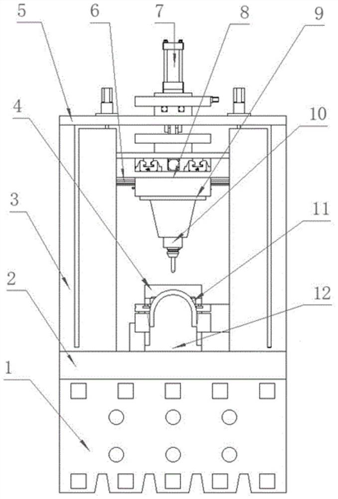
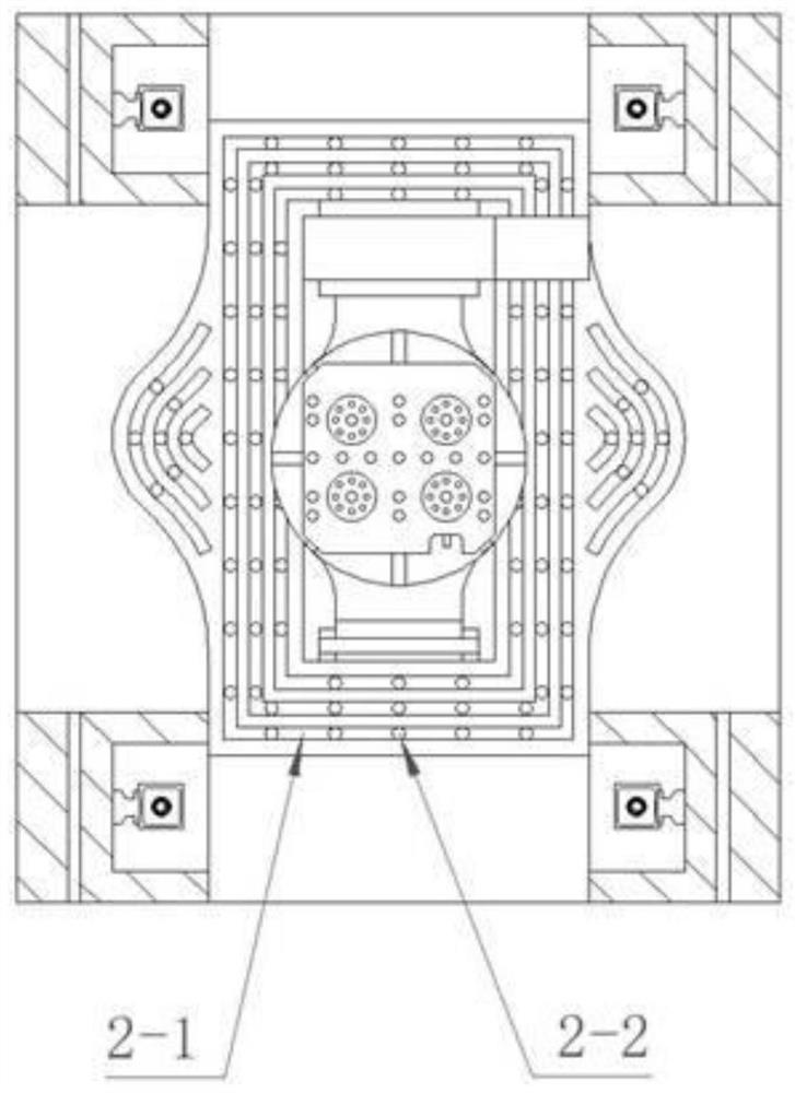
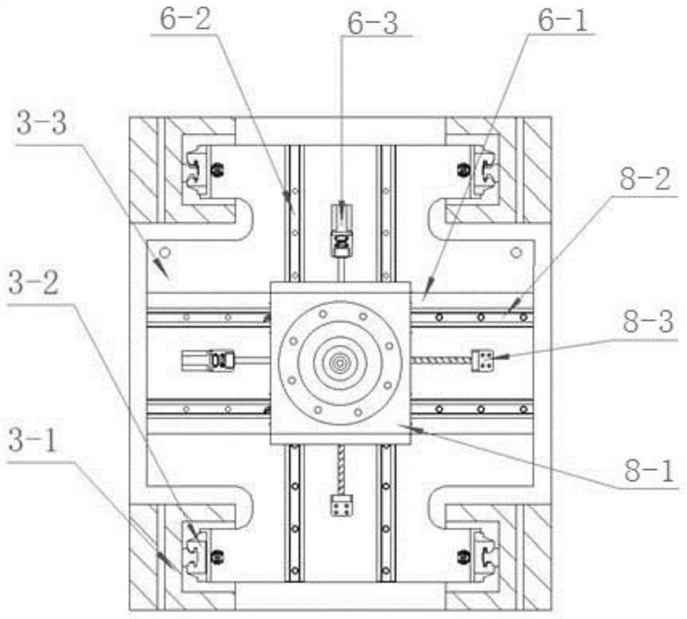
[0039] like Figure 1 to Figure 18As shown, an optical free-form surface precision milling machine tool includes a machine tool base 1, a machine base plate 2 is installed on the upper surface of the machine tool base 1 through a locking bolt assembly, and a Z-axis motion mechanism 3 and a cradle are installed on the upper surface of the machine tool base 2. Table 12, the optical free-form surface workpiece 4 is installed on the cradle table 12 through the workpiece fixture 11, the cradle table 12 can provide the A-axis rotary motion and the C-axis rotary motion of the machine tool, the Z-axis motion mechanism 3 is installed on the top of the machine tool top plate 5, the machine tool A gravity balance device is installed on the top plate 5; the upper surface of the bottom plate 2 of the machine tool is provided with a milling waste liquid col...


PUM


Abstract

An optical free-form surface precision milling machine tool, which belongs to the technical field of optical free-form surface manufacturing and precision machining, includes a machine tool base, the upper surface of the machine tool base is equipped with a machine tool base plate through an anti-loosening bolt assembly, and a Z-axis motion mechanism is installed on the upper surface of the machine tool base plate And the cradle worktable, the optical free-form surface workpiece is installed on the cradle workbench through the workpiece fixture, the machine tool top plate is installed on the top of the Z-axis motion mechanism, and the gravity balance device is installed on the machine tool top plate; the milling waste liquid collection is provided on the surface of the machine tool bottom plate There is a waste liquid collection hole at the bottom of the waste liquid collection tank, and the waste liquid collection hole is discharged through the pipeline to recycle the milling waste liquid; the Z-axis motion mechanism is sequentially installed with a Y-axis motion mechanism, an X-axis motion mechanism, and a spindle box. and spindle components. The machine tool has excellent rigidity, strength and stability. The anti-loosening bolt assembly used is a "bolt in the bolt" structure, which can ensure the stable static and dynamic characteristics of the machine tool.

Description

technical field [0001] The invention relates to the technical field of optical free-form surface manufacturing and precision machining, in particular to an optical free-form surface precision milling and milling machine tool. Background technique [0002] In the entire process chain of optical free-form surface processing, precision milling has a great influence on the surface and sub-surface quality of optical free-form surfaces, and its processing effect will directly determine the efficiency and feasibility of subsequent processing such as grinding and polishing. Therefore, the development of an optical free-form surface precision milling machine has become one of the key factors to improve the manufacturing capability of optical free-form surfaces, and the coupling of multiple factors such as high stiffness, large damping and long-term stability in the design of optical free-form surface milling machines has also made it an extremely important factor at present. One of t...

Claims


Application Information

Patent Timeline
Patent Type & Authority Patents(China)
IPC IPC(8): B23C3/00B23Q1/01B23Q1/25
CPCB23C3/00B23Q1/01B23Q1/015B23Q1/017B23Q1/25Y02P70/10
Inventor 李奇
Owner 李奇
Why Eureka
Try Eureka