Valve chamber cover cap structure capable of avoiding lubricating oil impact

A valve chamber and lubricating oil technology, which is applied to engine components, machines/engines, housings, etc., can solve the problems of inability to buffer impact force, large destructive force of the rubber coating, and easy damage to the rubber coating, so as to increase the life and ease Effect of processing and weakening force

Pending Publication Date: 2021-03-16
GUANGXI YUCHAI MASCH CO LTD
View PDF0 Cites 0 Cited by
  • Summary
  • Abstract
  • Description
  • Claims
  • Application Information

AI Technical Summary

Problems solved by technology

[0003] In the existing design of the valve chamber cover, the engine uses the valve chamber cover to cover the cylinder head, the valve chamber cover and the cylinder head are sealed with glue, and the vacuum pump connected to the oil return port of the valve chamber cover The oil outlet of the engine oil is just facing the glue layer. When the vacuum pump returns oil from the engine oil, it cannot buffer the impact of the vacuum pump’s oil discharge, and it is easy to damage the glue layer between the valve chamber cover and the cylinder head.
The transmission shaft of the vacuum pump is directly proportional to the engine speed. The higher the engine speed, the greater the oil return flow rate, the higher the oil flow rate, the greater the destructive power to the glue layer, and the easier it is to cause oil leakage.

Method used


Image

  • Valve chamber cover cap structure capable of avoiding lubricating oil impact
  • Valve chamber cover cap structure capable of avoiding lubricating oil impact
  • Valve chamber cover cap structure capable of avoiding lubricating oil impact

Examples


Embodiment 1

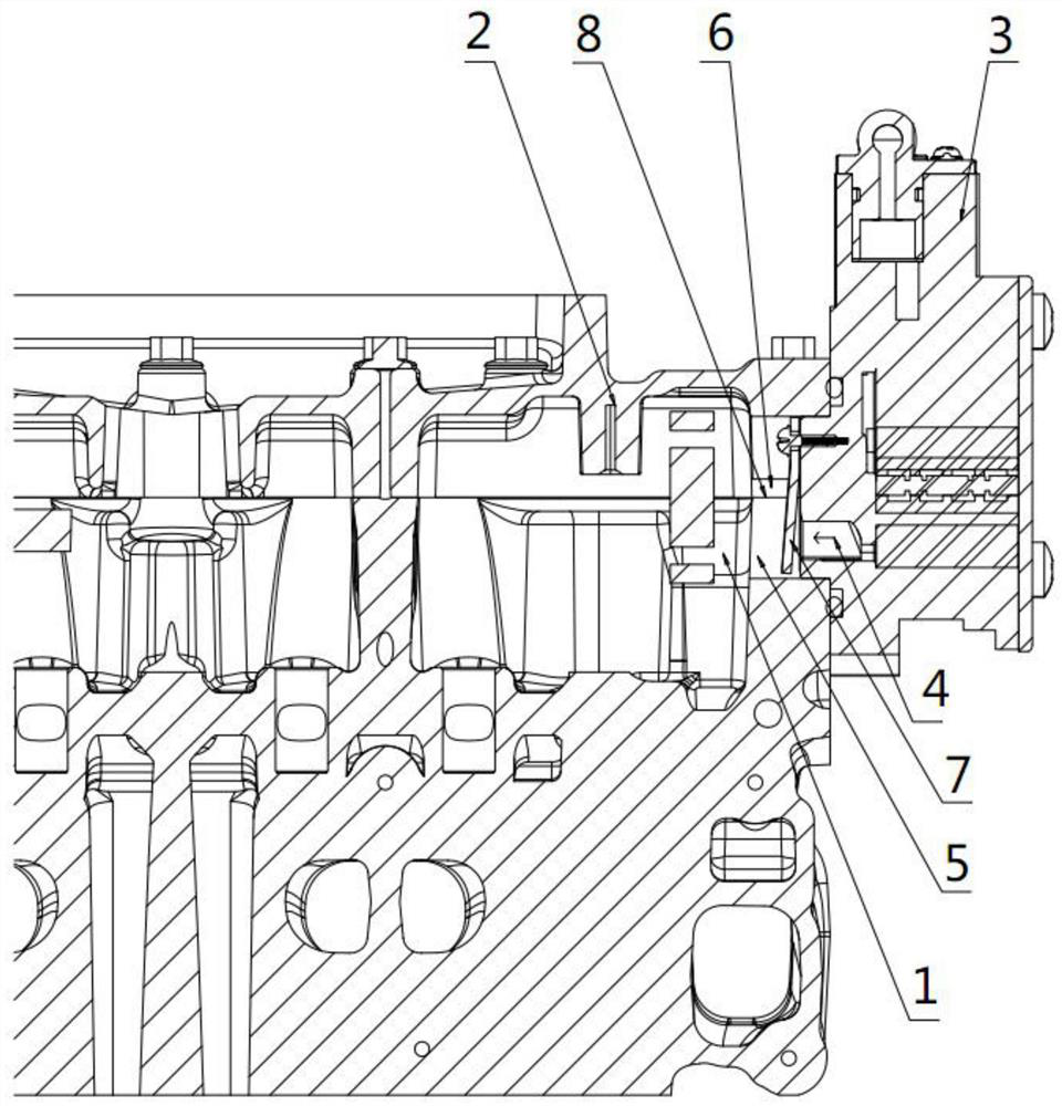
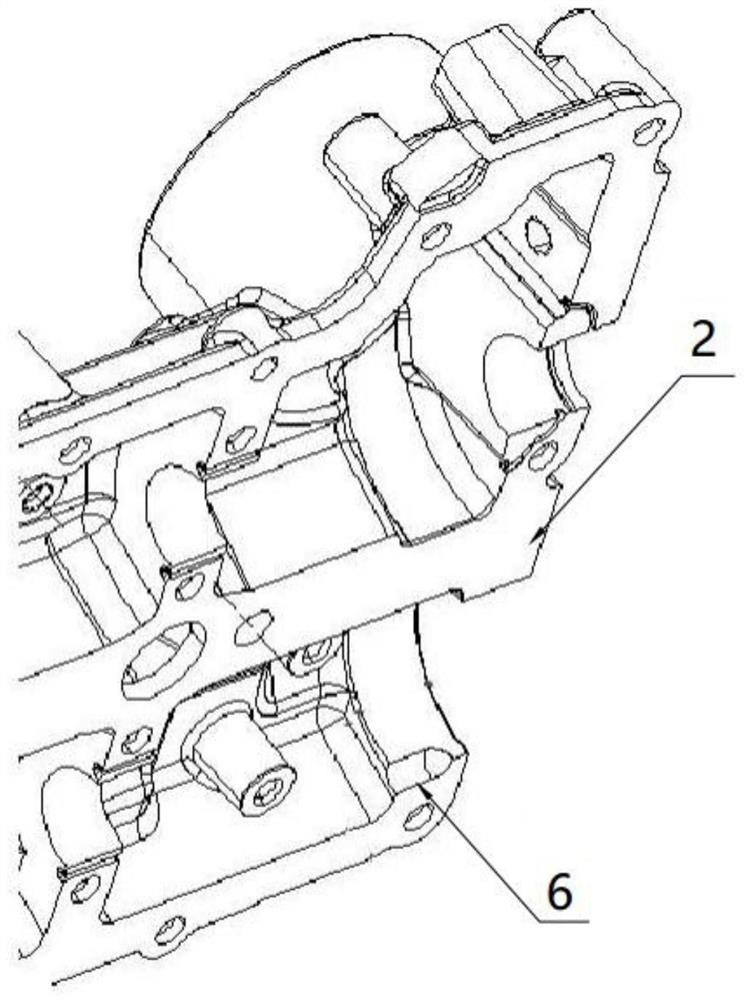
[0020] A valve chamber cover structure that avoids the impact of lubricating oil according to the specific implementation manner of this scheme, such as figure 1 , 3 As shown, it includes a valve chamber cover 2 covered on the upper end of the engine cylinder head 1, and the rear end surface of the valve chamber cover 2 is provided with an oil return port 5 connected to the oil outlet 4 of the vacuum pump 3. The oil outlet 4 extends into the oil return port 5 and enters the inner chamber of the valve chamber cover 2; an oil drain groove 6 is arranged on the inner edge of the bottom surface of the valve chamber cover 2 that cooperates with the engine cylinder head 1. The oil drain groove 6 is close to the oil return port 5 and extends along the direction of the oil outlet 4. The inner cavity of the oil drain groove 6 is an arc surface, and the inner side of the arc surface faces the valve chamber cover 2. Inner cavity; the oil return port 5 is provided with a blocking plate 7;...

Embodiment 2

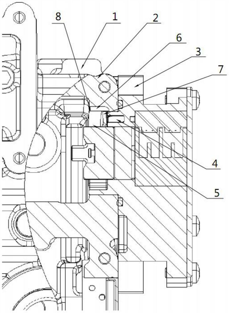
[0023] Such as figure 2 As shown, on the basis of Embodiment 1, one end of the oil drain groove 6 in this embodiment extends toward the oil return port 5 and at least partially surrounds the outer surface of the oil outlet 4 . When the engine starts to run, the engine oil flowing through the vacuum pump 3 comes out from the position of the baffle 7 and flows to the left and right sides. As the engine speed increases, the oil flow rate increases and the impact force becomes stronger. The piece 7 flows into the oil return port 5, a part of which is blocked by the baffle piece 7, rushes to the joint surface of the valve chamber cover 2 and the cylinder head, and washes the glue layer on the joint surface, and then flows into the oil return port 5. By extending the oil drain groove 6 to the periphery of the oil outlet 4, the impact of engine oil on the rubber coating layer 8 at the end of the oil outlet 4 is further reduced.

[0024] As a preferred technical solution of this emb...


PUM


Abstract

The invention discloses a valve chamber cover cap structure capable of avoiding lubricating oil impact. The valve chamber cover cap structure comprises a valve chamber cover cap covering the upper endof an engine cylinder cover, the rear end surface of the valve chamber cover cap is provided with an engine oil return port connected with an engine oil outlet of a vacuum pump, and engine oil of theengine oil outlet enters an inner cavity of the valve chamber cover cap; an oil drainage groove is formed in the inner edge of the bottom surface of the valve chamber cover cap matched with the engine cylinder cover, the oil drainage groove is close to the engine oil outlet of the vacuum pump and extends in the direction of the engine oil outlet, an inner cavity of the oil drainage groove is an arc surface, and the inner side of the arc surface faces the inner cavity of the valve chamber cover cap; a blocking piece is arranged on the engine oil outlet of the vacuum pump; and the oil drainagegroove is located in the side of the blocking piece, and the length direction of the oil drainage groove is perpendicular to a blocking surface of the blocking piece. According to the valve chamber cover, the oil drainage groove is adopted, the engine oil returned by the vacuum pump can be prevented from directly impacting a gluing layer, the service life of the gluing layer is prolonged, and engine oil leakage is prevented.

Description

technical field [0001] The invention relates to the technical field of engine manufacturing, in particular to a valve chamber cover structure which avoids the impact of lubricating oil. Background technique [0002] The vacuum pump is used as the power source of the vehicle's brake assist and steering assist. The vacuum pump is connected to the engine cylinder head, driven by the engine camshaft to drive the drive shaft to rotate, and the vacuum pump operates to generate a vacuum pressure difference. The lubrication of the vacuum pump needs to be taken from the engine oil circuit. The existing vacuum pump lubricating oil circuit is usually connected by a rubber hose, which is costly, and the rubber hose is easy to age, which affects the lubrication effect. In order to enhance the lubricating effect and make the engine more compact, the oil inlet and oil outlet of the vacuum pump can also be directly connected with the oil outlet and oil return port in the internal oil circui...

Claims


Application Information

Patent Timeline
IPC IPC(8): F02F7/00
CPCF02F7/0065
Inventor 蒋维樊心龙
Owner GUANGXI YUCHAI MASCH CO LTD
Why Eureka
Try Eureka