Novel SF6 equipment three-way valve state display device
A state display and three-way valve technology, applied in the direction of valve devices, mechanical equipment, engine components, etc., can solve problems such as SF6 equipment damage, misjudgment of SF6 gas chamber opening and closing status, and influence on power supply reliability, etc., to eliminate errors The effect of judging risks, improving inspection efficiency, and ensuring safe operation
- Summary
- Abstract
- Description
- Claims
- Application Information
AI Technical Summary
Problems solved by technology
Method used
Image

Examples
Embodiment 1
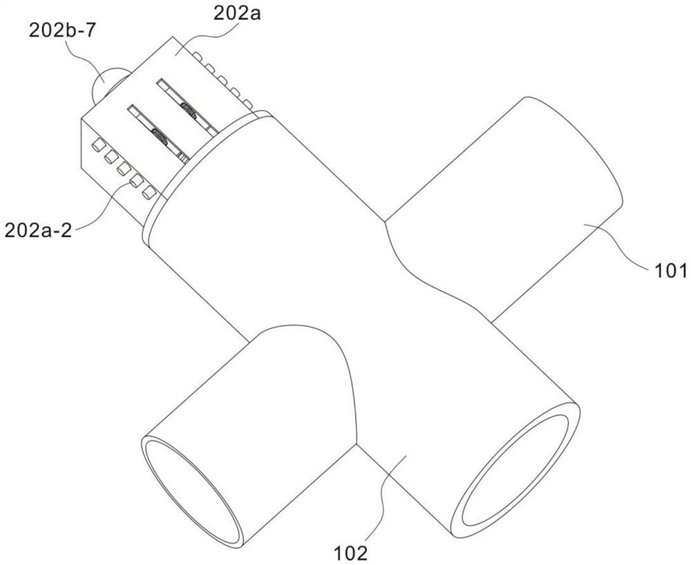
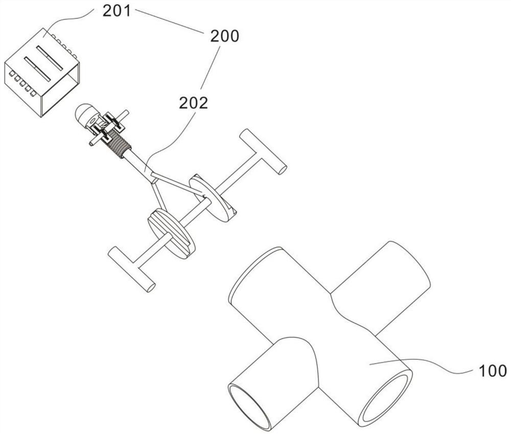
[0031] refer to Figure 1-7 , provides a schematic diagram of the overall structure of a new type of SF6 equipment three-way valve status display device, as shown in figure 1 , a new SF6 equipment three-way valve state display device includes a three-way valve body 100, the three-way valve body 100 includes a first pipeline 101 and a second pipeline 102, the first pipeline 101 is perpendicular to the second pipeline 102, and;
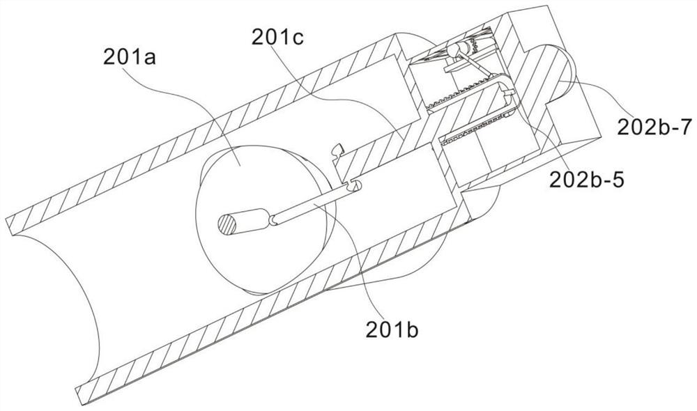
[0032] Visual adjustment unit 200; the visual adjustment unit 200 includes an opening and closing mechanism 201 and a visual mechanism 202. The opening and closing mechanism 201 includes a stepped block 201a and a strut 201b arranged on the side end surface of the stepped block 201a. The stepped block 201a is located in the first pipe 101, and the moving rod 201c connected to the other end of the supporting rod 201b, the two sides of the moving rod 201c are connected with the supporting rod 201b through movable links, when the moving rod 201c moves up a...
Embodiment 2
[0037] refer to Figure 1-7 , provides a schematic diagram of the overall structure of a new type of SF6 equipment three-way valve status display device, as shown in figure 1 , a new SF6 equipment three-way valve state display device includes a three-way valve body 100, the three-way valve body 100 includes a first pipeline 101 and a second pipeline 102, the first pipeline 101 is perpendicular to the second pipeline 102, and;
[0038] Visual adjustment unit 200; the visual adjustment unit 200 includes an opening and closing mechanism 201 and a visual mechanism 202. The opening and closing mechanism 201 includes a stepped block 201a and a strut 201b arranged on the side end surface of the stepped block 201a. The stepped block 201a is located in the first pipe 101, and the moving rod 201c connected to the other end of the supporting rod 201b, the two sides of the moving rod 201c are connected with the supporting rod 201b through movable links, when the moving rod 201c moves up a...
PUM
 Abstract
Description
Claims
Application Information
 - Generate Ideas
- Intellectual Property
- Life Sciences
- Materials
- Tech Scout
- Unparalleled Data Quality
- Higher Quality Content
- 60% Fewer Hallucinations
Browse by: Latest US Patents, China's latest patents, Technical Efficacy Thesaurus, Application Domain, Technology Topic, Popular Technical Reports.
© 2025 PatSnap. All rights reserved.Legal|Privacy policy|Modern Slavery Act Transparency Statement|Sitemap|About US| Contact US: help@patsnap.com