
A self-cleaning equipment for uniform heating of a coal-fired heat-conducting oil furnace

A heat-conducting oil furnace and uniform heating technology, which is applied to lighting and heating equipment, heat storage heaters, fluid heaters, etc., can solve the problems of low efficiency and manpower consumption, and achieve guaranteed efficiency, improved cleaning efficiency, and reasonable design Effect

Active Publication Date: 2022-02-08
TIANCHANG CHENGTAI MEDICINAL MACHINERY EQUIP CO LTD
View PDF0 Cites 0 Cited by
  • Summary
  • Abstract
  • Description
  • Claims
  • Application Information

AI Technical Summary

Problems solved by technology

[0004] The purpose of the present invention is to solve the problem of labor-intensive and low efficiency in the prior art, and propose a self-cleaning equipment for uniform heating of coal-fired heat-conducting oil furnace

Method used


Image

  • A self-cleaning equipment for uniform heating of a coal-fired heat-conducting oil furnace
  • A self-cleaning equipment for uniform heating of a coal-fired heat-conducting oil furnace
  • A self-cleaning equipment for uniform heating of a coal-fired heat-conducting oil furnace

Examples


Embodiment 1

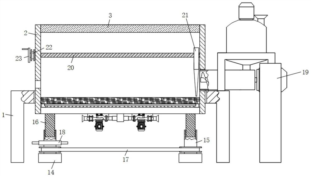
[0029] refer to Figure 1-5 , a self-cleaning equipment for uniform heating of a coal-fired heat-conducting oil furnace, including a mounting frame-1, a cylindrical hole is opened on the top surface of the mounting frame-1, the inner wall of the cylindrical hole is fixed with a heating chamber 2 through screws, and the inner wall of the heating chamber 2 is fixed on the top side A heat transfer plate 3 is connected, and a combustion assembly is arranged on the lower side of the inner wall of the heating chamber 2. The combustion assembly includes a hollow dish 4, and a support plate 5 is fixed on both sides of the top surface of the hollow dish 4 through screws, and a support plate 5 is fixed on the top of the support plate 5 through screws. The combustion net 6 and the top surface of the hollow dish 4 are also connected with an air injection pipe 7, and the two support plates 5 are provided with a chute 8 at one end close to each other. An air intake pipe 10 is connected, and...

Embodiment 2

[0032] Such as figure 1 and 5 As shown, this embodiment is basically the same as Embodiment 1. Preferably, the bulk material assembly 21 includes a mounting plate 211, and a threaded hole 212 is opened through the front and rear sides of the upper end of the mounting plate 211, and the screw rod 20 is screwed into the threaded hole 212. , the bottom surface of the mounting plate 211 is also fixedly connected with a dispersing rod 213 .

[0033] Multiple dispersing rods 213 are provided and evenly distributed on the bottom surface of the mounting plate 211 , and the front and rear sides of the mounting plate 211 are attached to the inner wall of the heating chamber 2 .

[0034] In this embodiment, by rotating the screw mandrel 20 to move a plurality of dispersing rods 213 in the heating chamber 2 to realize the dispersing operation of the coal, so that the coal can fully contact with the air, thereby ensuring the combustion rate of the coal.

Embodiment 3

[0036] Such as figure 1 As shown, this embodiment is basically the same as Embodiment 1. Preferably, an ignition port is provided at the lower end of the heating chamber 2 .

[0037] In this embodiment, an ignition port is provided at the lower end side of the heating chamber 2, so as to facilitate the ignition operation during combustion.


PUM


Abstract

The invention discloses a self-cleaning equipment for uniform heating of a coal-fired heat-conducting oil furnace. The device comprises a first installation frame. A cylindrical hole is formed on the top surface of the first installation frame. The inner wall of the cylindrical hole is fixed with a heating chamber through screws. A heat transfer plate is fixedly connected, and a combustion component is fixedly connected to the lower side of the inner wall of the heating chamber. The combustion component includes a hollow dish. Support plates are fixed on both sides of the top surface of the hollow dish through screws, and a combustion mesh is fixed on the top of the support plate through screws. , the top surface of the hollow dish is also connected with a jet pipe, and two support plates are provided with a chute at one end that is close to each other, a partition plate is slidably connected in the chute, and an air inlet pipe is connected through the center of the bottom surface of the hollow pan. , the bottom surface of the hollow dish is also fixed with an air pump through screws. The invention has reasonable design, stable operation of the device, convenient cleaning of the residue after combustion, and uniform feeding, which well ensures the efficiency of coal-fired combustion.

Description

technical field [0001] The invention relates to the technical field of mechanical coal-fired heat-conducting oil maintenance, in particular to a self-cleaning equipment for uniform heating of a coal-fired heat-conducting oil furnace. Background technique [0002] The coal-fired heat-conducting oil furnace uses coal, heavy oil, light oil or combustible liquid as fuel. After the coal-fired heat-conducting oil furnace is used, its inner wall often contains many residues. If these residues are not removed in time, it will cause the next fuel failure. Insufficient combustion, so it is very important to clean the coal-fired heat transfer oil furnace. [0003] Most of the existing cleaning methods are to manually clean the inner wall of the combustion chamber through auxiliary tools at the charging button, and disassemble and clean the machine after a period of time during use, which is inconvenient to operate and greatly wastes the time for cleaning the coal-fired heat-conducting ...

Claims


Application Information

Patent Timeline
Patent Type & Authority Patents(China)
IPC IPC(8): F24H7/00F24H9/00F24H9/18B02C13/14B02C13/30
CPCF24H7/007F24H9/00F24H9/18B02C13/14B02C13/30
Inventor 周金山
Owner TIANCHANG CHENGTAI MEDICINAL MACHINERY EQUIP CO LTD
Learn More