
Weld joint nondestructive testing device for pipeline flaw detection

A non-destructive testing and piping technology, applied in heating devices, spraying devices, using non-combustion exothermic chemical reactions to generate heat, etc., can solve problems such as inability to spray permeate through pipelines, accumulation of impurities inside the device, and affecting detection results, etc. , to achieve scientific and reasonable structure, improve uniformity, and increase utilization efficiency

Inactive Publication Date: 2021-03-16
徐子明
View PDF0 Cites 9 Cited by
  • Summary
  • Abstract
  • Description
  • Claims
  • Application Information

AI Technical Summary

Problems solved by technology

[0004] The present invention provides a weld non-destructive testing device for flaw detection of pipelines, which can effectively solve the problem that the penetration solution cannot be sprayed uniformly on the pipelines, which affects the detection results, and at the same time, when cleaning the outer surface of the pipelines, Impurities cannot be filtered and impurities accumulate inside the device

Method used


Image

  • Weld joint nondestructive testing device for pipeline flaw detection
  • Weld joint nondestructive testing device for pipeline flaw detection
  • Weld joint nondestructive testing device for pipeline flaw detection

Examples


Embodiment

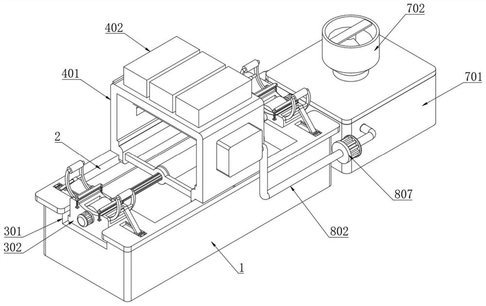
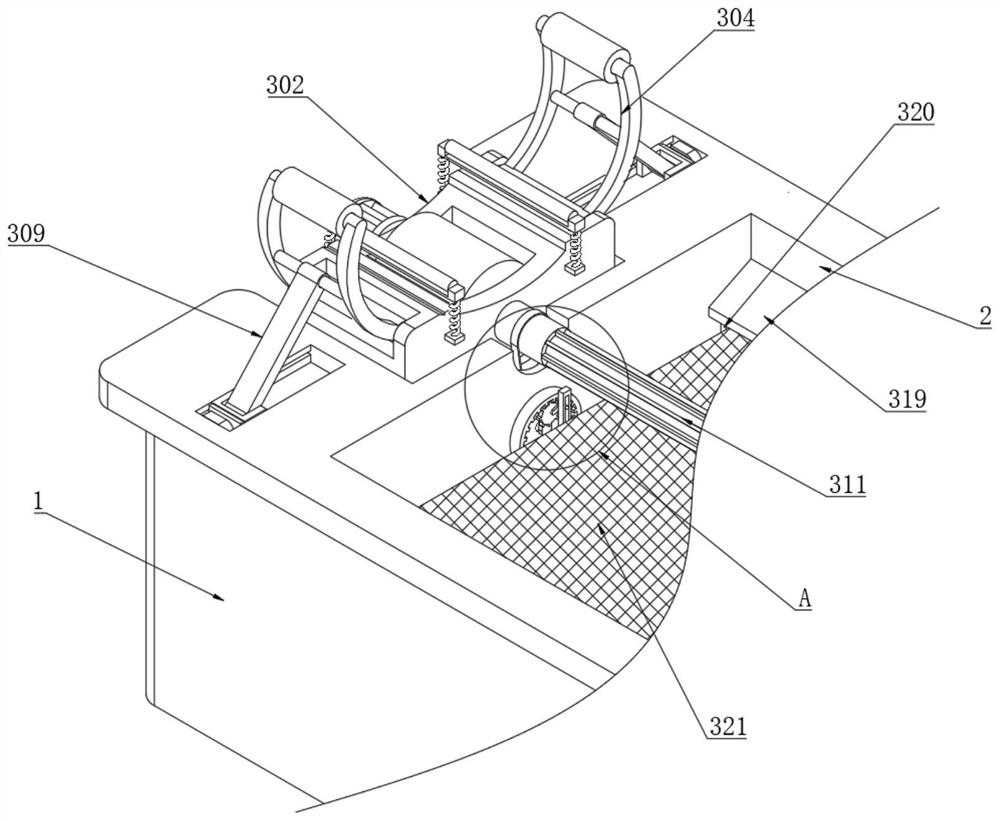
[0040] Example: such as Figure 1-10 As shown, the present invention provides a technical solution based on a weld non-destructive testing device for pipeline flaw detection, including a machine base 1, a liquid storage tank 2 is opened at the middle of the top of the machine base 1, and the inside of the liquid storage tank 2 A waste water discharge mechanism 5 is provided;

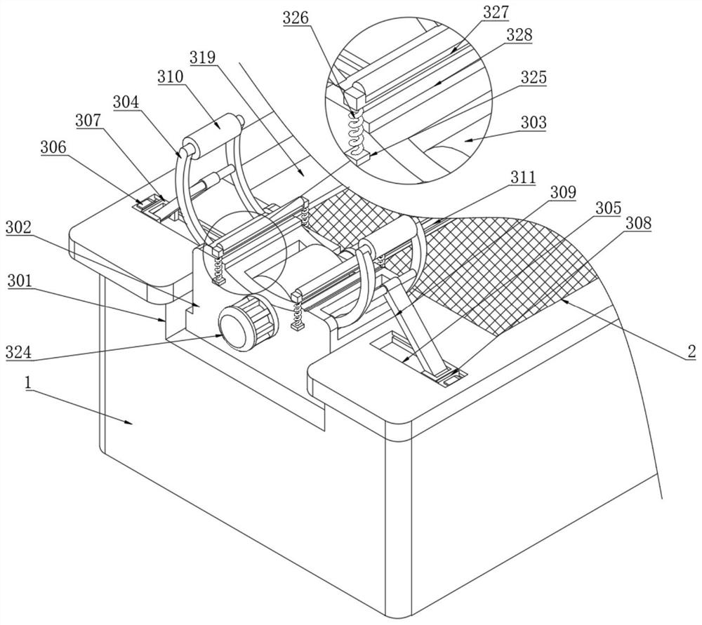
[0041] The top of the machine base 1 is symmetrically provided with a limiting and screening mechanism 3 at the positions corresponding to both sides of the liquid storage tank 2;

[0042] A high-efficiency spraying mechanism 4 is arranged at the top of the base 1 corresponding to the top of the liquid storage tank 2;

[0043] The limit and screening mechanism 3 includes an embedded groove 301, a support seat 302, a support wheel 303, a clamping force arm 304, a chute 305, an electromagnet 306, a slider 307, a magnetic strip 308, a push plate 309, and a limit roller 310 , rotating shaft 311, notch 312,...


PUM


Abstract

The invention discloses a weld joint nondestructive testing device for pipeline flaw detection. The device comprises a machine base, a liquid storage tank is formed in the middle of the top end of themachine base, a wastewater discharging mechanism is arranged in the liquid storage tank, and limiting and screening mechanisms are symmetrically arranged at the positions, corresponding to the two sides of the liquid storage tank, of the top end of the machine base, an efficient spraying mechanism is arranged at the top end, corresponding to the top of the liquid storage tank, of the machine base; each limiting and screening mechanism comprises an embedded groove, a supporting seat and a bearing wheel. The device is scientific and reasonable in structure and safe and convenient to use, the limiting and screening mechanisms are arranged, side guide rollers are pressed to descend through the self-weight of a pipeline, electrode plates at the bottom ends of the side guide rollers are attached to electrode plates at the top ends of bottom blocks, power is supplied to an electromagnet, and electromagnets are matched with magnetic strips, and sliding blocks are pushed to slide, meanwhile, the magnetic force of the electromagnets is increased according to the current conveying strength, and the pushing force of the electromagnets for pushing the magnetic strips is increased, therefore the moving effect of the sliding blocks is guaranteed.

Description

technical field [0001] The invention relates to the technical field of pipeline flaw detection, in particular to a weld nondestructive testing device for pipeline flaw detection. Background technique [0002] Pipeline flaw detection is a method to check whether the internal quality of welded joints of pipelines is qualified. Commonly used pipeline non-destructive testing methods include X-ray flaw detection, ultrasonic flaw detection, magnetic particle flaw detection, penetrant flaw detection, eddy current flaw detection, gamma ray flaw detection and fluorescent flaw detection, etc. method, among which penetrant flaw detection is a flaw detection method that uses penetrating liquid to display surface defects of components. Remove the excess penetrant on the surface, and then apply a layer of imaging agent, so that the penetrant remaining in the defect is absorbed and the defect is displayed on the surface; [0003] However, the existing penetrant detection device cannot spr...

Claims


Application Information

Patent Timeline
Patent Type & Authority Applications(China)
IPC IPC(8): G01N21/91C02F9/04B01D33/03F24V30/00F26B23/10B05B13/02
CPCG01N21/91C02F1/66C02F1/001B01D33/0353F24V30/00F26B23/10B05B13/0228B01F33/83613
Inventor 徐子明
Owner 徐子明
Learn More