
Composite electricity testing grounding device and overhead line system electricity testing grounding control system

A grounding device and composite technology, applied in the field of rail transit, can solve problems such as high labor intensity, potential safety hazards, and restrictions on electric passenger cars

Pending Publication Date: 2021-03-16
CHENGDU YUNDA TECH CO LTD
View PDF0 Cites 2 Cited by
  • Summary
  • Abstract
  • Description
  • Claims
  • Application Information

AI Technical Summary

Problems solved by technology

[0003] At present, after the catenary is powered off, the electric inspection method is manually operated, that is, before the electric inspection, it is necessary to manually check the electric pole once, and after the catenary isolating switch is opened and the power is cut off, the operator will check Lift the electric pole along the direction of the track, use the metal head of the electric pole to touch and close to the catenary for three times of electric inspection, and confirm that there is no sound and light alarm on the electric pole, indicating that there is no electricity (if there is sound, light and sound signal, it means that there is still electricity) , but the voltage level cannot be judged, and the ground crew driver needs to raise the bow to detect the voltage)
[0004] This traditional electric inspection method completely relies on manual work, which is labor-intensive and low in efficiency, which greatly restricts the development of electric bus repair and maintenance in the direction of mechanization, automation, and intelligent control. The reason for requiring three electric inspections is that Human error causes missed inspection, which has certain safety hazards and is not conducive to safe production

Method used


Image

  • Composite electricity testing grounding device and overhead line system electricity testing grounding control system
  • Composite electricity testing grounding device and overhead line system electricity testing grounding control system
  • Composite electricity testing grounding device and overhead line system electricity testing grounding control system

Examples


Embodiment 1

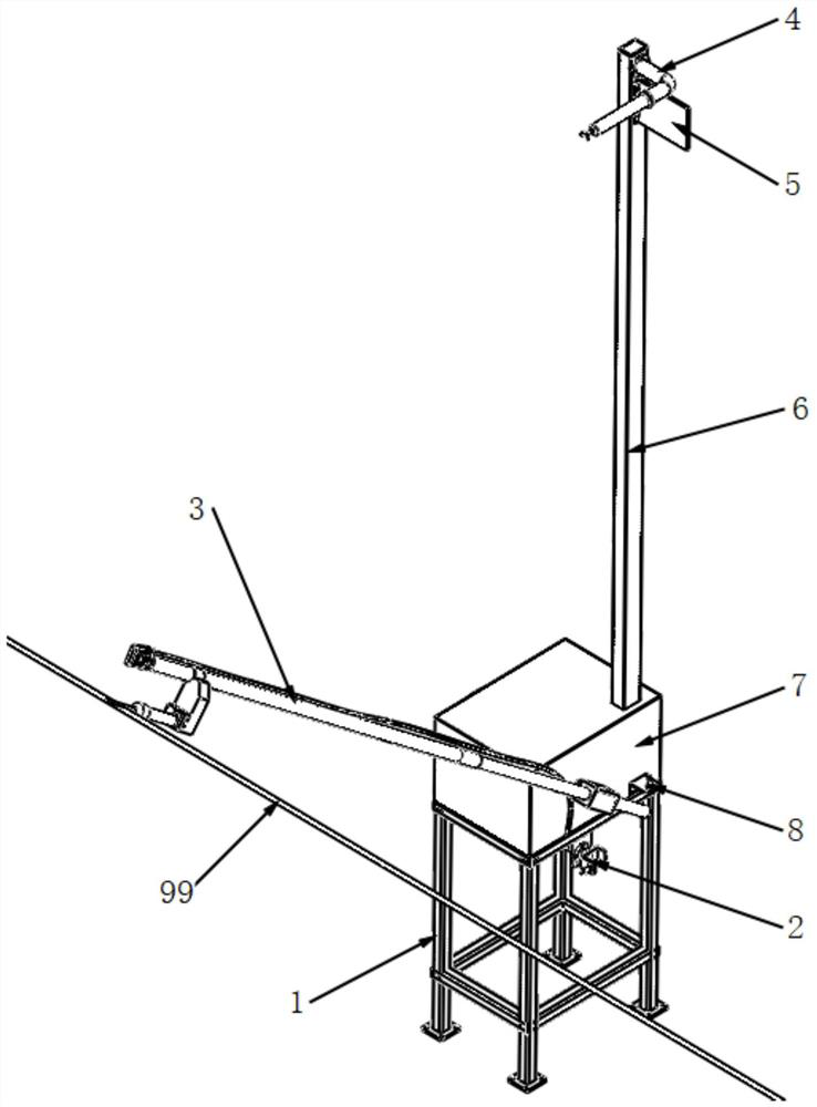
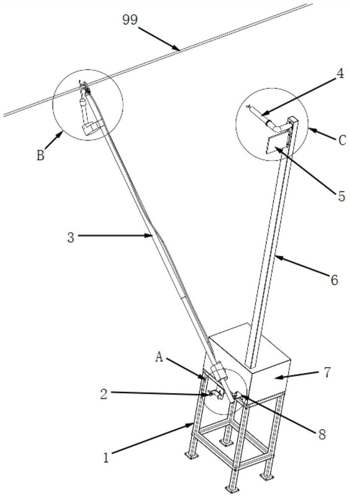
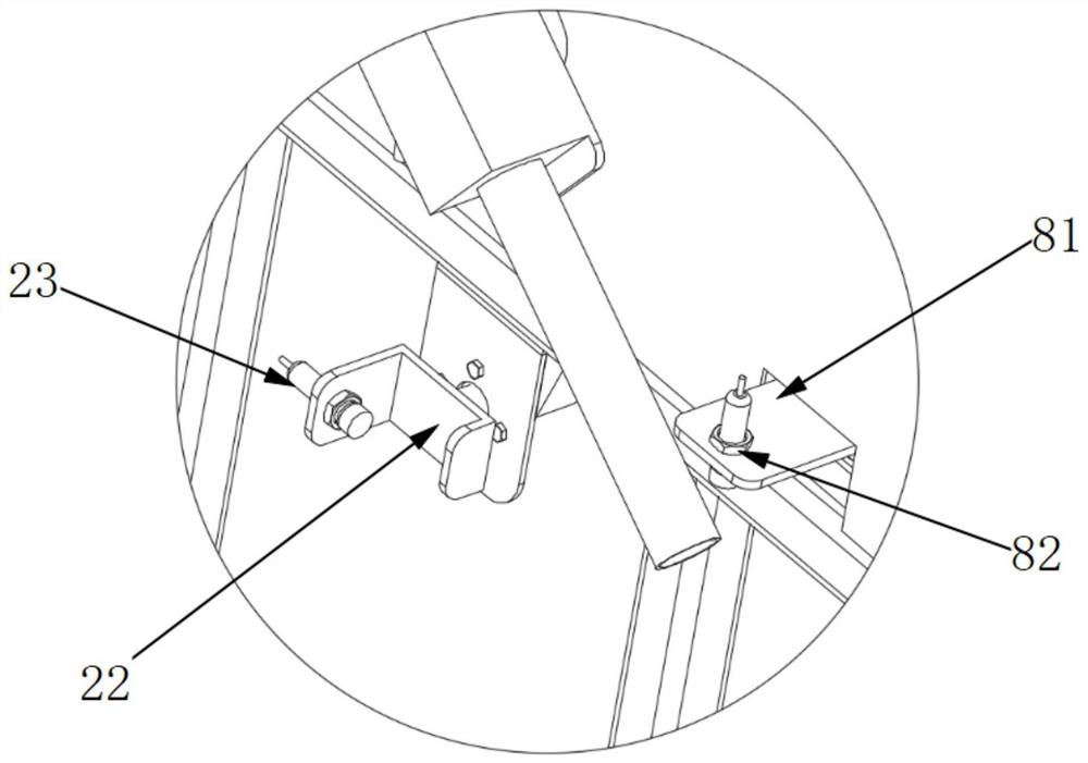
[0061] like Figure 1 to Figure 14 As shown, a composite electric test grounding device includes a mounting bracket 1, a driving device 7 fixed on the mounting bracket 1, and an electric testing ground rod assembly 3 connected to the output end of the driving device 7;

[0062] The electrical testing grounding rod assembly 3 includes a first insulating rod 32, a grounding knife 39 fixed on the first insulating rod 32, a detector 36 that is rotatably connected with the first insulating rod 32 and used for electrical testing, as a detector 36 metal rods 37 with metal heads;

[0063] The driving device 7 is connected to the rear end of the first insulating rod 32 and is used to drive the first insulating rod 32 to swing, and the rotating shaft forming the rotatable connection and the rotating shaft forming the swinging are parallel to each other;

[0064] The grounding knife 39 and the detector 36 are all arranged on the front end of the first insulating rod 32, and the metal ba...

Embodiment 2

[0072] like Figure 1 to Figure 14 As shown, this embodiment is further limited on the basis of Embodiment 1: as a technical solution to facilitate the reliable and insulated connection between the detector 36 and the first insulating rod 32, it is set as follows: the electric test grounding rod assembly 3 also includes a connecting block 34 and a second insulating rod 35, the connecting block 34 is fixed on the first insulating rod 32, the rear end of the second insulating rod 35 is rotatably connected to the connecting block 34, and the detector 36 The rear end is fixedly connected with the front end of the second insulating rod 35. In this solution, the second insulating rod 35 is used as an insulation isolation between the detector 36 and the first insulating rod 32, such as for isolating the detector 36 and the grounding wire 33, and the connecting block 34 can be a metal piece. To realize the reliable connection of two insulating rods.

[0073] Regarding the grounding ...

Embodiment 3

[0086] This embodiment is further limited on the basis of any one of the technical solutions provided by any one of the above embodiments, such as Figure 1 to Figure 14 As shown, in order to facilitate the realization of automation and intelligence or improve the level of automation and intelligence, this embodiment also discloses a catenary 99 electrical inspection and grounding control system, including the composite electrical inspection and grounding device described in any one of the above, Also includes:

[0087] Electric testing unit: connected with the detector 36, used for detecting the voltage value or voltage level on the catenary 99;

[0088] Detection unit: used for detecting the resistance value and charged state of the grounding wire 33 on the grounding knife 39;

[0089] Manipulation unit: used to realize the human-computer interaction with the compound electrometric grounding device.


PUM


Abstract

The invention discloses a composite electricity testing grounding device and an overhead line system electricity testing grounding control system. The device comprises an installation bracket, a driving device and an electricity testing grounding rod assembly, wherein the electricity testing grounding rod assembly comprises a first insulating rod, a grounding knife, a detector and a metal rod, thedriving device is connected with the rear end of the first insulating rod and is used for driving the first insulating rod to swing, the grounding switch and the detector are both arranged at the front end of the first insulating rod, the front end of the metal rod is located on the opening side of the grounding switch when the metal rod is in a free state, and the opening side and the metal rodare arranged side by side in the extending direction of an overhead line system. The system is based on the device. By adopting the device and the system provided by the scheme, electricity testing and grounding intellectualization and automation can be realized conveniently, electricity testing and grounding equipment can be integrated, electricity testing and grounding are completed in a continuous action process, and compared with the prior art, the device and the system have the characteristics that electricity testing and grounding are completed more reliably and safely.

Description

technical field [0001] The invention relates to the technical field of rail transit, in particular to a composite electric inspection and grounding device and a catenary electric inspection and grounding control system. Background technique [0002] In the field of rail transit, there are electrified railway contact nets in locomotive depot maintenance yards, bullet train depot (station) maintenance depots, rolling stock depot maintenance depots, passenger whole station maintenance depots, subway depot maintenance depots and other places. Before overhaul and equipment maintenance, etc., it is necessary to perform operations such as disconnecting the switch and disconnecting the power, checking the electricity, releasing the remaining electricity, and grounding. [0003] At present, after the catenary is powered off, the electric inspection method is manually operated, that is, before the electric inspection, it is necessary to manually check the electric pole once, and after...

Claims


Application Information

Patent Timeline
IPC IPC(8): H01R11/11H01R11/14H01R43/00G01R35/00G01R19/145
CPCG01R19/145G01R35/007H01R11/11H01R11/14H01R43/00B60M1/02
Inventor 沈兆国江海涛刘东洪郑显明
Owner CHENGDU YUNDA TECH CO LTD
Learn More