MEMS microphone and micro-electromechanical structure

A technology of micro-electromechanical structure and hole structure, applied in the direction of diaphragm structure, electrostatic transducer microphone, etc., can solve the problem of short circuit between the back plate and the vibrating membrane, and achieve the effect of saving process time, improving limitations and reducing costs.

Inactive Publication Date: 2021-03-16
MEMSENSING MICROSYST SUZHOU CHINA
View PDF7 Cites 2 Cited by
  • Summary
  • Abstract
  • Description
  • Claims
  • Application Information

AI Technical Summary

Problems solved by technology

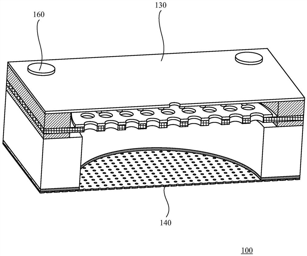
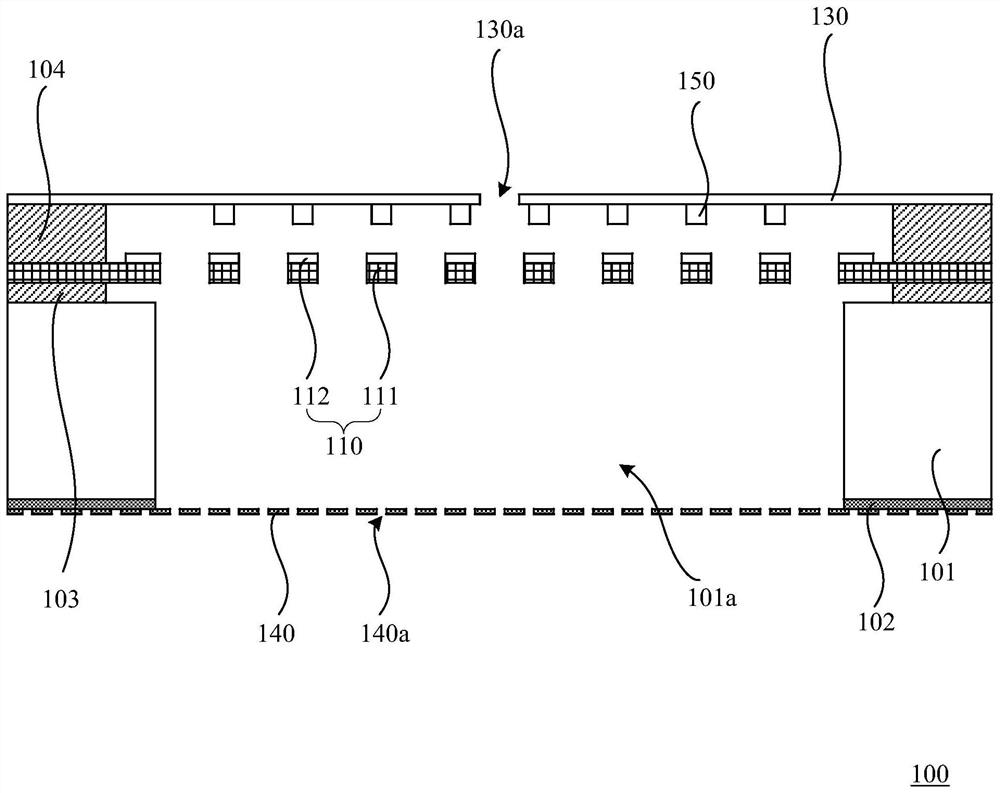
[0005] In view of this, the present invention provides an improved MEMS microphone and micro-electromechanical structure, by setting a protective layer in the micro-electromechanical structure, thereby preventing foreign matter from entering the gap between the back plate and the vibrating membrane through the through hole of the back plate , thus improving the short circuit between the back plate and the vibrating membrane in the MEMS structure caused by foreign matter

Method used


Image

  • MEMS microphone and micro-electromechanical structure
  • MEMS microphone and micro-electromechanical structure
  • MEMS microphone and micro-electromechanical structure

Examples


Embodiment Construction

[0045] Hereinafter, the present invention will be described in more detail with reference to the accompanying drawings. In the various figures, identical elements are indicated with similar reference numerals. For the sake of clarity, various parts in the drawings have not been drawn to scale. Also, some well-known parts may not be shown. For the sake of simplicity, the semiconductor structure obtained after several steps can be described in one figure.

[0046]It should be understood that when describing the structure of a device, when a layer or a region is referred to as being "on" or "over" another layer or another region, it may mean being directly on another layer or another region, or Other layers or regions are also included between it and another layer or another region. And, if the device is turned over, the layer, one region, will be "below" or "beneath" the other layer, another region.

[0047] If it is intended to describe the situation of being directly on an...


PUM


Abstract

The invention discloses an MEMS microphone and a micro electro mechanical system structure. The micro-electro-mechanical structure is applied to the front sound inlet MEMS microphone, and comprises asubstrate which is provided with a top surface, a bottom surface and a back cavity penetrating through the top surface and the bottom surface, wherein the top surface and the bottom surface are opposite; a back polar plate which is positioned on the top surface of the substrate and is provided with at least one through hole; a vibrating diaphragm, wherein the vibrating diaphragm and the back polarplate form a variable capacitor; and a protective layer which is located on the bottom surface of the substrate and used for preventing foreign matter from entering the gap between the back polar plate and the vibrating diaphragm through the back cavity and the through hole, and the vibrating diaphragm covers the back polar plate so as to prevent the foreign matter from entering the gap from thesurface, away from the back polar plate, of the vibrating diaphragm.

Description

technical field [0001] This application relates to the field of semiconductor device manufacturing, and more specifically, to MEMS microphones and micro-electromechanical structures. Background technique [0002] Devices manufactured based on Micro Electro Mechanical Systems (MEMS) are called MEMS devices. MEMS devices mainly include a vibrating membrane and a back plate, and there is a gap between the vibrating membrane and the back plate. The change of air pressure will cause the deformation of the vibrating membrane, and the capacitance value between the vibrating membrane and the electrode plate will change, which will be converted into an electrical signal output. [0003] In the traditional MEMS microphone structure, it is mainly composed of two parallel plate capacitor structures, the back plate and the vibrating membrane. Among them, the back plate is on the top, and the vibrating film is on the bottom. The sound hole is located on the substrate of the package struc...

Claims


Application Information

Patent Timeline
Patent Type & Authority Applications(China)
IPC IPC(8): H04R19/04H04R7/02
CPCH04R7/02H04R19/04
Inventor 荣根兰孙恺孟燕子胡维
Owner MEMSENSING MICROSYST SUZHOU CHINA
Why Eureka
Try Eureka