Methanol cracking reaction equipment convenient to adjust
A technology of reaction equipment and methanol cracking, applied in chemical/physical processes, chemical instruments and methods, etc., can solve the problems of low efficiency and manpower consumption, and achieve the effects of accelerated cooling, improved efficiency, and fast conversion speed
- Summary
- Abstract
- Description
- Claims
- Application Information
AI Technical Summary
Problems solved by technology
Method used
Image

Examples
Embodiment 1
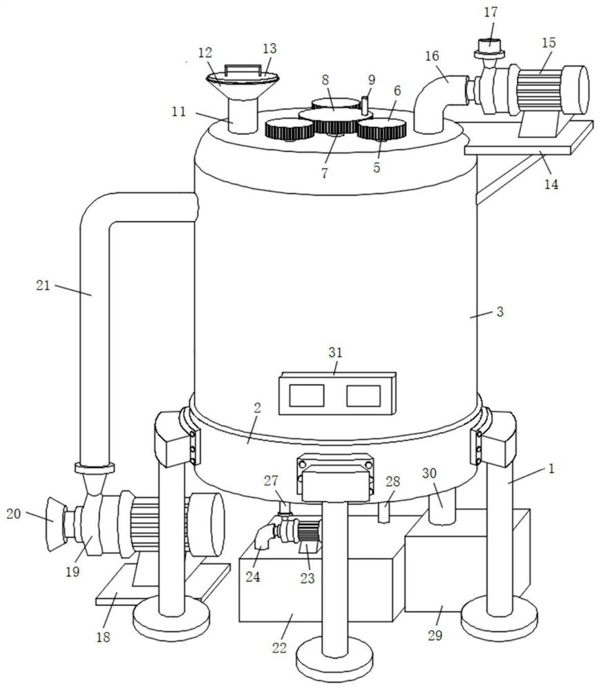
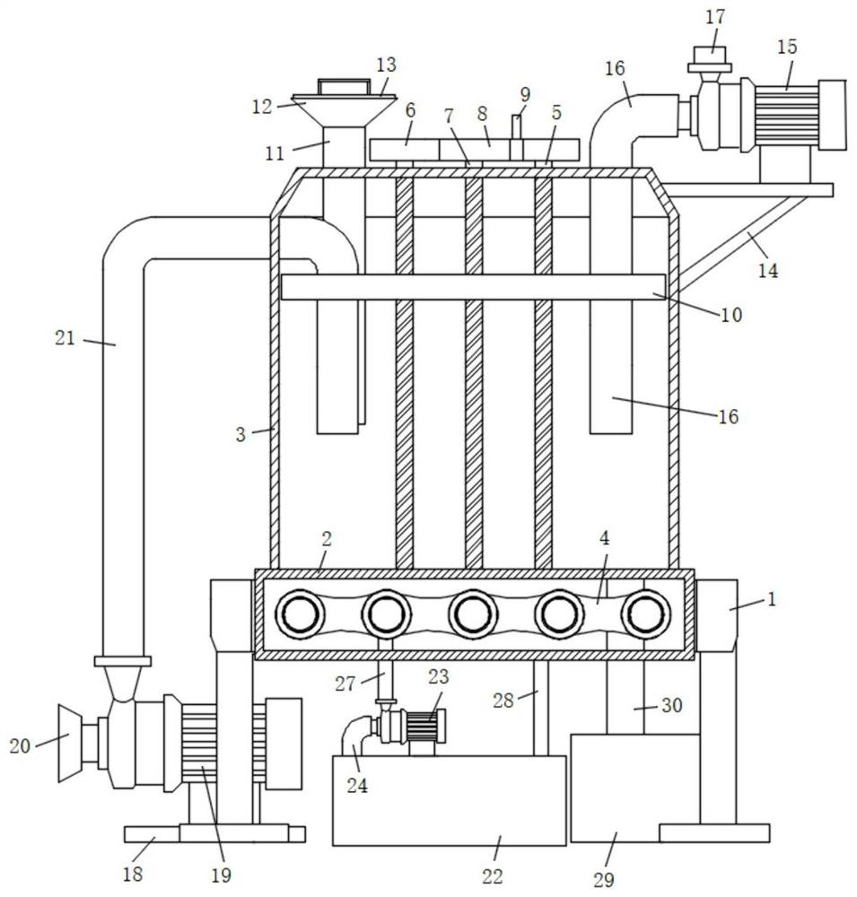
[0029] refer to Figure 1-4 , a methanol cracking reaction device that is easy to adjust, including a support base 1, a heating chamber 2 is fixed on the inner wall of the upper end of the support base 1 through screws, a cracking barrel 3 is glued to the center of the top of the heating chamber 2, and the inner wall of the heating chamber 2 is also fixed. A temperature control assembly 4, a threaded rod 5 is rotatably connected between the top surface of the cracking barrel 3 and the top surface of the heating chamber 2, and the upper ends of the threaded rod 5 extend to the outside of the cracking barrel 3 and are fixedly connected with a driven wheel 6 at the end. The center position of the top surface of the barrel 3 is also connected with a driving rod 7 in rotation, the top of the driving rod 7 is fixedly connected with a driving wheel 8 through screws, and the driven wheels 6 are meshed with the driving wheel 8, and the top side of the driving wheel 8 is also fixedly con...
Embodiment 2
[0032] Such as figure 1 and 4 As shown, this embodiment is basically the same as Embodiment 1. Preferably, the monitoring assembly 31 includes a mounting dish 32, which is fixed at the lower end of the front side wall of the cracking barrel 3 by screws, and the two sides of the rear end of the mounting dish 32 are respectively A pressure detector 33 and a temperature detector 34 are installed, and a display panel 35 is installed on the front end surface of the installation dish 32 .
[0033] The detection ends of the pressure detector 33 and the temperature detector 34 both extend to the inside of the cracking barrel 3 , and the output ends of the pressure detector 33 and the temperature detector 34 are electrically connected to the input end of the display panel 35 .
[0034] In the present embodiment, by installing the monitoring assembly 31 on the front side of the cracking barrel 3, when the device is running, the pressure detector 33 and the temperature detector 34 can m...
Embodiment 3
[0036] Such as figure 1 and 2 As shown, this embodiment is basically the same as Embodiment 1. Preferably, multiple support seats 1 are provided and evenly distributed on the outer wall of the middle part of the heating chamber 2 , and the sealing plug 13 is clamped and fixed on the inner wall of the upper end of the feeding funnel 12 .
[0037] In this embodiment, the sealing plug 13 is clamped and fixed on the feeding funnel 12, so that the sealing plug 13 is more convenient to take and place.
PUM
 Abstract
Description
Claims
Application Information