Convenient-to-adjust positioning device for machine tool accessory mold and method

A technology for positioning devices and adjusting parts, which is applied in positioning devices, metal processing mechanical parts, manufacturing tools, etc., can solve the problems of uneven side surfaces of workpieces, unfavorable clamping and fixing, etc., and achieve the effect of strong practicability

Inactive Publication Date: 2021-03-19
GUANGYUAN BORUI PRECISION TECH CO LTD
View PDF9 Cites 10 Cited by
  • Summary
  • Abstract
  • Description
  • Claims
  • Application Information

AI Technical Summary

Problems solved by technology

[0003] When processing machine tool accessories, it is necessary to fix the machine tool accessories on the upper part of the workbench for positioning. The traditional fixing method is to use fixtures to fix the accessory blanks on the upper part of the workbench. Different fixtures need to be set for different workpieces. After all, the surfaces of different workpieces are different. , there are still many workpieces with uneven sides, which is not conducive to clamping and fixing. In view of the above problems, a conveniently adjustable positioning device and method for machine tool parts molds are now provided

Method used


Image

  • Convenient-to-adjust positioning device for machine tool accessory mold and method
  • Convenient-to-adjust positioning device for machine tool accessory mold and method
  • Convenient-to-adjust positioning device for machine tool accessory mold and method

Examples


Embodiment Construction

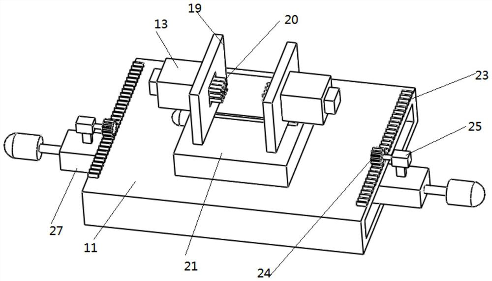
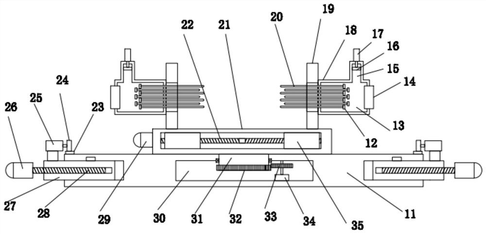
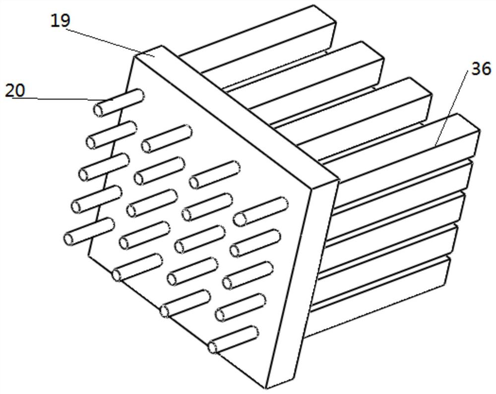
[0021] In describing the present invention, it should be understood that the terms "center", "longitudinal", "transverse", "upper", "lower", "front", "rear", "left", "right", " The orientations or positional relationships indicated by "vertical", "horizontal", "top", "bottom", "inner" and "outer" are based on the orientations or positional relationships shown in the drawings, and are only for the convenience of describing the present invention and Simplified descriptions, rather than indicating or implying that the device or element referred to must have a particular orientation, be constructed and operate in a particular orientation, and thus should not be construed as limiting the invention. In addition, the terms "first", "second", etc. are used for descriptive purposes only, and should not be understood as indicating or implying relative importance or implicitly specifying the quantity of the indicated technical features. Thus, a feature defined as "first", "second", etc. ...


PUM


Abstract

The invention discloses a convenient-to-adjust positioning device for a machine tool accessory mold and a method. The positioning device comprises a fixed base arranged at the machining position of amachine tool in a sliding mode, wherein plane position adjusting pieces used for adjusting the position of the fixed base are arranged at the two sides of the fixed base; a supporting table used for supporting a workpiece is arranged in the middle of the upper end of the fixed base; a rotary driving piece used for driving the supporting table to rotate is arranged at the upper end of the fixed base; a clamping piece used for clamping the workpiece is arranged at the upper end of the supporting table; the clamping piece comprises mounting plates symmetrically arranged at the two sides of the upper end of the supporting table; and the lower ends of the two mounting plates are connected to a clamping pushing piece used for driving the two mounting plates to get close to each other or get awayfrom each other. The positioning device is designed for overcoming the defects of an existing device, the horizontal position of the workpiece can be adjusted, and the workpiece can be rotationally adjusted; and in addition, the shape of the clamping face can be adjusted, the clamping requirements of the workpieces of various shapes are met, and the practicability is high.

Description

technical field [0001] The invention relates to the technical field of mechanical processing equipment, in particular to a conveniently adjustable positioning device and method for molds of machine tool accessories. Background technique [0002] Machine tools refer to machines that manufacture machines, also known as machine tools or machine tools. They are customarily referred to as machine tools. They are generally divided into metal cutting machine tools, forging machine tools, and woodworking machine tools. There are many ways to process mechanical parts in modern machinery manufacturing. In addition to cutting, There are also casting, forging, welding, stamping, extrusion, etc., but all parts with higher precision requirements and finer surface roughness requirements generally need to be final processed on machine tools by cutting methods. Playing a major role in construction, the machine tool has a complex structure and needs to be composed of many accessories. [000...

Claims


Application Information

Patent Timeline
Patent Type & Authority Applications(China)
IPC IPC(8): B23Q3/08
CPCB23Q3/082
Inventor 赵学刚叶斌杨志伟李子剑向订吉曹勇
Owner GUANGYUAN BORUI PRECISION TECH CO LTD
Why Eureka
Try Eureka