Diamond surface polygonal polishing device

A polishing device and polygonal technology, applied in the field of grinding and polishing, can solve the problems of angle deflection error, excessively increasing the number of surface deflection, pitting corrosion, etc., and achieve the effect of reducing re-clamping

Inactive Publication Date: 2021-03-19
SHANGHAI ZHENGSHI TECH CO LTD
View PDF5 Cites 0 Cited by
  • Summary
  • Abstract
  • Description
  • Claims
  • Application Information

AI Technical Summary

Problems solved by technology

[0002] After the traditional diamond polygon is processed, the diamond is clamped and then moved for grinding. Friction occurs between the surface to be ground and the grinding plane, thereby producing a grinding effect. This grinding method has two disadvantages. One is that there are many polygons. After grinding a surface, you need to adjust the attitude of the clamping frame to change the grinding angle. As many surfaces as there are diamonds, you need to adjust as many times. During the adjustment process, there is likely to be an accumulation of angle adjustment errors, which will affect the last few grinding contact angles. The accuracy of the grinding process causes size problems; another problem is: the surface to be ground is continuously ground, and there is a lot of frictional heat, which is easy to cause pitting corrosion. Can be idle, but can’t quickly replace another surface for grinding, because as mentioned above, there may be a slight angle deflection error when changing the grinding surface, so when the diamond has many unavoidable surface deflections, you can’t wait for the frictional heat to be lost During this period, the number of surface deflections will only increase, so the efficiency of the grinding process is low and the time is long

Method used


Image

  • Diamond surface polygonal polishing device
  • Diamond surface polygonal polishing device
  • Diamond surface polygonal polishing device

Examples


Embodiment Construction

[0025] The following will clearly and completely describe the technical solutions in the embodiments of the present invention with reference to the accompanying drawings in the embodiments of the present invention. Obviously, the described embodiments are only some, not all, embodiments of the present invention. Based on the embodiments of the present invention, all other embodiments obtained by persons of ordinary skill in the art without making creative efforts belong to the protection scope of the present invention.

[0026] see Figure 1-8 , the present invention provides technical solutions:

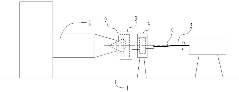
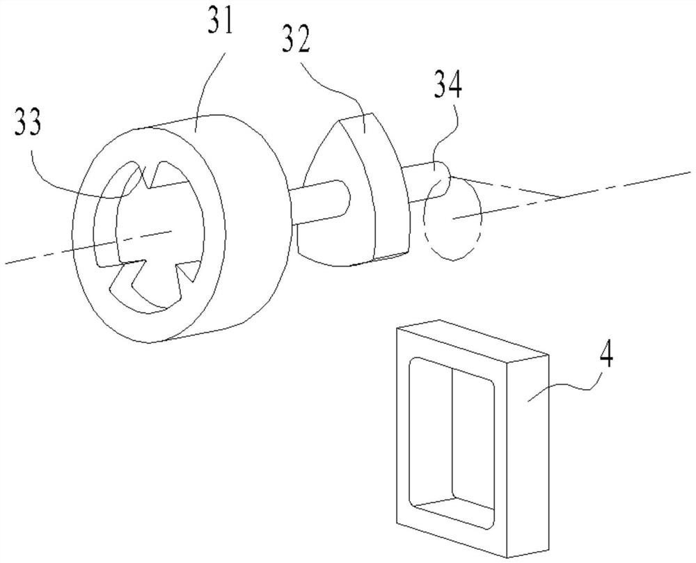
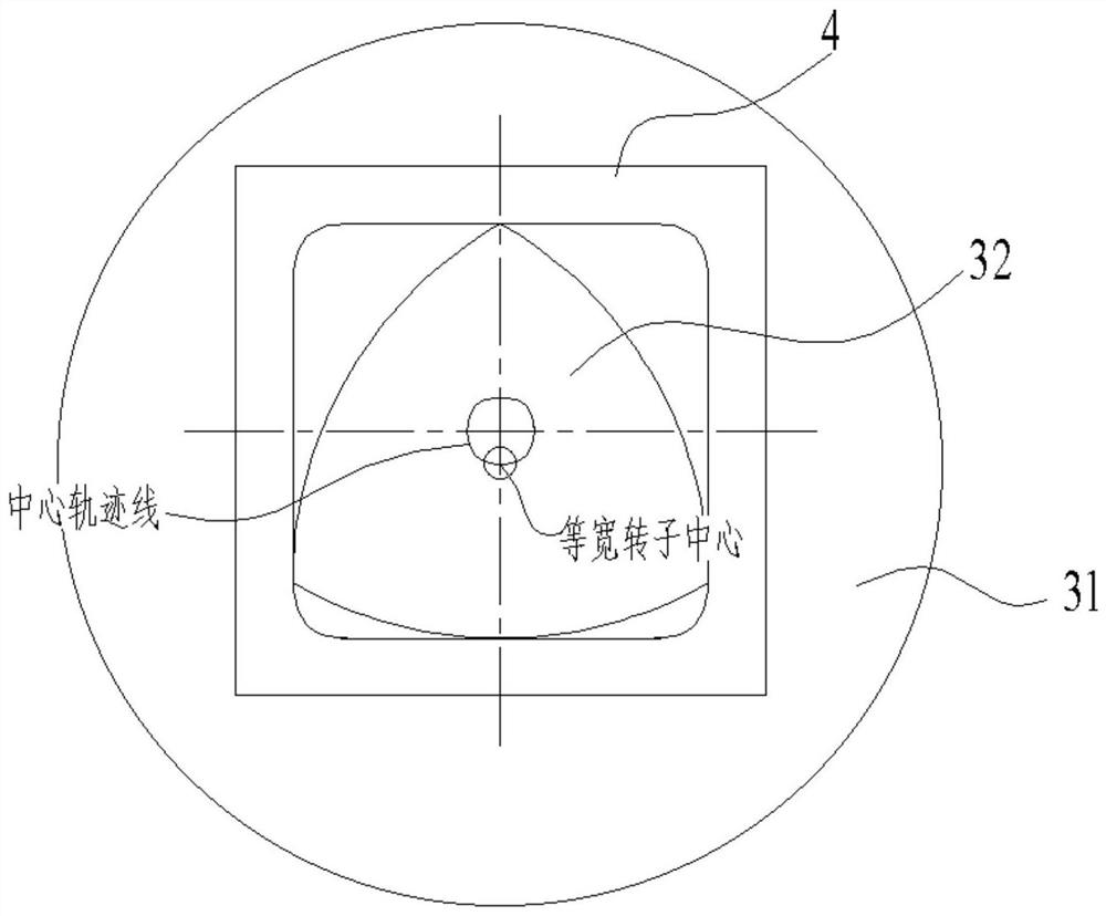
[0027] A diamond surface polygonal polishing device, including a base 1, a clamping frame 2, a rotor assembly 3, a fitting ring 4, a power shaft 5, a transmission shaft 6 and a universal coupling 7, a clamping frame 2, and a fitting ring 4 and the output part of the power shaft 5 are installed on the base 1, the clamping frame 2 clamps the diamond body 9 to be polished, the rotor a...


PUM


Abstract

The invention discloses a diamond surface polygon polishing device which comprises a base, a clamping frame, a rotor assembly, a fitting ring, a power shaft, a transmission shaft and a universal coupling. Output pieces of the clamping frame, the fitting ring and the power shaft are all installed on the base, the clamping frame clamps a diamond body to be polished, and the rotor assembly is rotatably supported by the fitting ring. One end of the rotor assembly is in transmission connection with the power shaft through the transmission shaft and the universal coupling, a grinding structure is arranged at the other end of the rotor assembly to be in contact with the surface of the diamond body, and the rotor assembly rotates to conduct grinding. The rotor assembly comprises a polishing wheel,an equal-width rotor, grinding tips and a relay shaft, the relay shaft penetrates through the center of the equal-width rotor and is connected to one end of a polishing wheel, a concave groove is formed in the other end of the polishing wheel, the grinding tips with the number equal to that of the edges of the equal-width rotor are centripetally arranged in the concave groove, the tip positions of the grinding tips coincide with corner positions of equal-width rotor in the axial direction, the outer contour of the equal-width rotor is an equal-width curve.

Description

technical field [0001] The invention relates to the technical field of grinding and polishing, in particular to a diamond surface polygonal polishing device. Background technique [0002] After the traditional diamond polygon is processed, the diamond is clamped and then moved for grinding. Friction occurs between the surface to be ground and the grinding plane, thereby producing a grinding effect. This grinding method has two disadvantages. One is that there are many polygons. After grinding a surface, you need to adjust the attitude of the clamping frame to change the grinding angle. As many surfaces as there are diamonds, you need to adjust as many times. During the adjustment process, there is likely to be an accumulation of angle adjustment errors, which will affect the last few grinding contact angles. The accuracy of the grinding process causes size problems; another problem is: the surface to be ground is continuously ground, and there is a lot of frictional heat, wh...

Claims


Application Information

Patent Timeline
Patent Type & Authority Applications(China)
IPC IPC(8): B24B29/02B24B37/00B24B37/27B24B37/34
CPCB24B29/02B24B37/00B24B37/27B24B37/34
Inventor 满卫东朱长征龚闯吴剑波蒋剑宏杨春梅
Owner SHANGHAI ZHENGSHI TECH CO LTD
Why Eureka
Try Eureka