unmanned aerial vehicle

A retractable device, unmanned aerial vehicle technology, used in ground devices, motor vehicles, aircraft parts, etc., can solve problems such as inability to lift and lower, and achieve the effects of reducing injury and wear, high safety, and prolonging service life

Active Publication Date: 2022-07-26
浙江科特勘测设计有限公司
View PDF11 Cites 1 Cited by
  • Summary
  • Abstract
  • Description
  • Claims
  • Application Information

AI Technical Summary

Problems solved by technology

[0002] For example, the publication number CN109703438A includes: a retractable cabin, which includes a cabin body and a cover body; the cabin body is hingedly connected with the cover body; The components are hingedly connected to the cabin; the first power device drives the cover to rotate relative to the cabin to open or close the retractable cabin; the second power device drives the locking part relative to the The cabin body rotates to fix the UAV or release the fixation of the UAV; the control module is electrically connected to the first power device and the second power device respectively; the disadvantage of this invention is that it cannot be lifted

Method used


Image

  • unmanned aerial vehicle
  • unmanned aerial vehicle
  • unmanned aerial vehicle

Examples


specific Embodiment approach 1

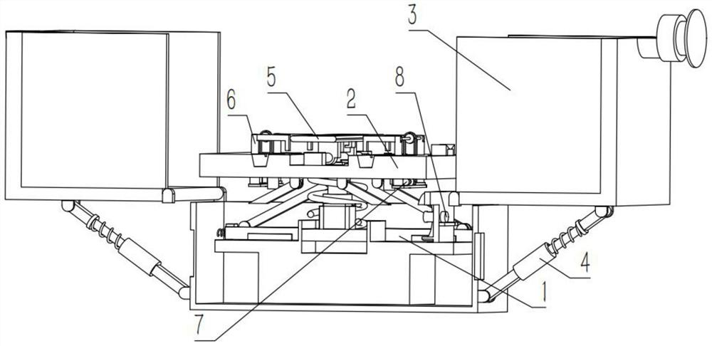
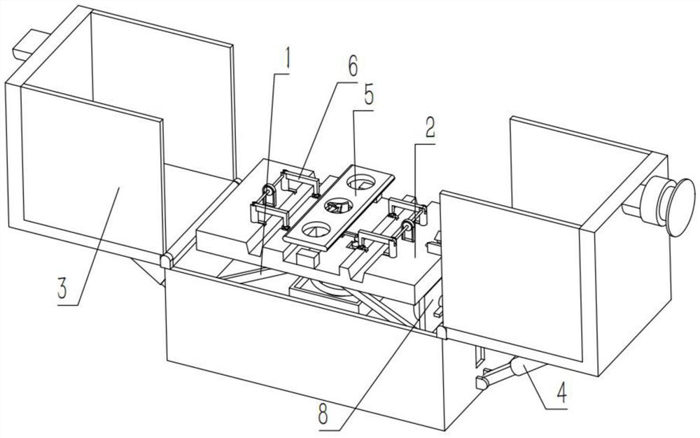
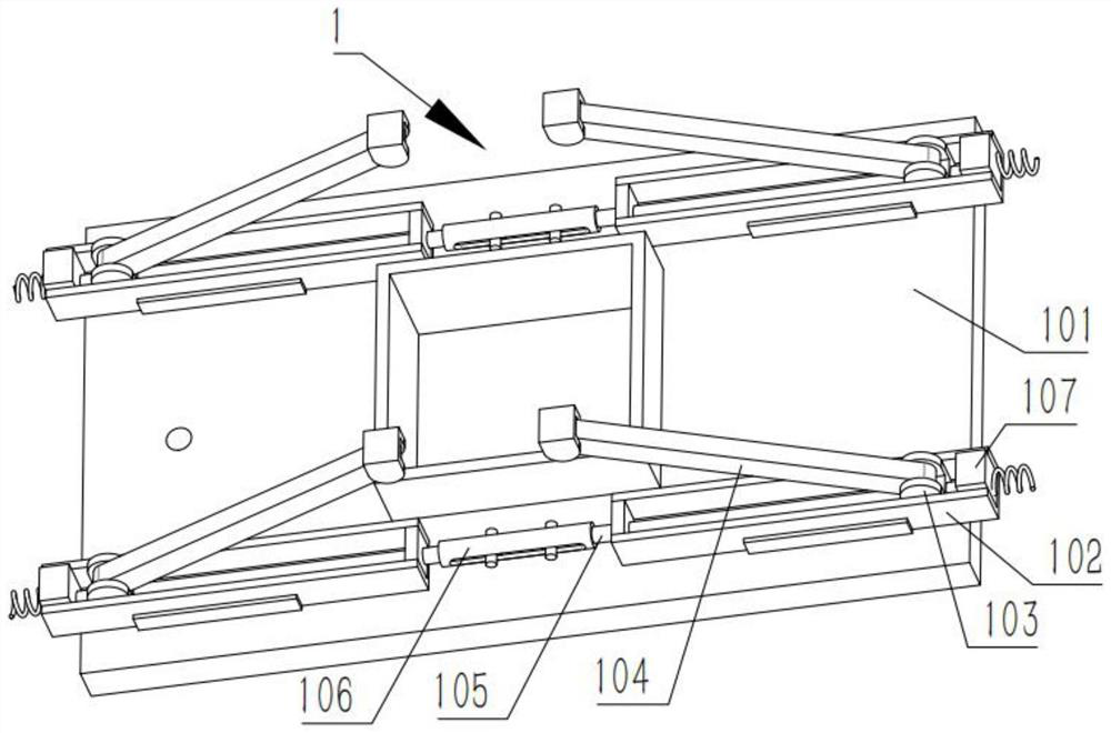
[0031] Combine below Figure 1-10 Describing this embodiment, an unmanned aerial vehicle retractable device includes an adjustment mechanism 1 and a damping mechanism 2. The adjustment mechanism 1 includes a support plate 101, a sliding chute 102, a sliding block 103, a first rotating rod 104, a thread The rod 105, the slotted sleeve 106 and the power motor 107, the two sliding chutes 102 are all slidably connected to the support plate 101, the two sliding blocks 103 are slidably connected to the two sliding chutes 102, the two first rotating The rods 104 are rotatably connected to the two sliding blocks 103 respectively, and the two threaded rods 105 are rotatably connected to the two sliding chutes 102 respectively. Connected in the slotted sleeve 106, the power motor 107 is fixedly connected to the right end of the sliding chute 102 at the right end, the threaded rod 105 at the right end is fixedly connected to the output shaft of the power motor 107, the two sliding chute ...

specific Embodiment approach 2

[0033] Combine below Figure 1-10 This embodiment will be described. This embodiment will further describe the first embodiment. The shock absorbing mechanism 2 further includes a fixing clip 202, a piston rod 203, a base 204, a shock absorbing spring 205 and a matching sleeve 206. The fixing clip 202 is fixedly connected to the lift. On the plate 201, the piston rod 203 is fixedly connected to the bottom end of the lifting plate 201, the piston rod 203 is slidably connected to the base 204, and the upper and lower ends of the shock-absorbing spring 205 are fixedly connected to the lifting plate 201 and the base 204 respectively. The sleeves 206 are all slidably connected in the lifting plate 201, the plurality of matching sleeves 206 are respectively connected in the lifting plate 201 through a plurality of springs, and the base 204 is slidably connected to the supporting plate 101;

[0034] It can reduce the damage and wear of the UAV due to bumps during the transportation p...

specific Embodiment approach 3

[0035] Combine below Figure 1-10 Describing this embodiment, this embodiment further describes Embodiment 2. The UAV retractable device further includes a casing mechanism 3, and the casing mechanism 3 includes a rotating cover 301, a half-section thread 302, a box body 303, The power supply 304 , the threaded head 305 and the threaded ring 306 , the two rotating covers 301 are rotatably connected to the box body 303 , the two half-section threads 302 are fixedly connected to the two rotating covers 301 respectively, and the power supply 304 is fixedly connected in the box body 303 . , the threaded head 305 is fixedly connected to the upper end of the half thread 302 at the right end, the threaded ring 306 and the threaded head 305 are threaded for transmission, the support plate 101 is fixedly connected in the box body 303, and the plurality of sliding chutes 102 are connected to the box body 303 by springs on the inner wall;

[0036] When closing the device, turn the two r...


PUM


Abstract

The invention relates to the technical field of unmanned aerial vehicle (UAV) retractable and unmanned aerial vehicles, and more particularly relates to an unmanned aerial vehicle (UAV) retractable device, comprising an adjustment mechanism and a damping mechanism, wherein the adjustment mechanism includes a support plate, a sliding chute, a sliding block and a rotating rod , threaded rod, slotted sleeve and power motor, the two sliding chutes are slidably connected to the support plate, the two sliding blocks are slidably connected to the two sliding chutes, and the two rotating rods are rotatably connected to the two On the sliding block, the two threaded rods are respectively connected to the two sliding chutes, and the two threaded rods are respectively threaded with the sliding block. The right end of the sliding chute, the threaded rod at the right end is fixedly connected to the output shaft of the power motor, the two sliding chute, the sliding block, the rotating rod and the threaded rod, as well as the slotted sleeve and the power motor are the lifting part, and also A set of raised parts are arranged at the rear end of the support plate.

Description

technical field [0001] The invention relates to the technical field of unmanned aerial vehicle (UAV) retraction and release, and more particularly relates to a UAV retracting and releasing device. Background technique [0002] For example, Publication No. CN109703438A includes: a storage compartment, which includes a compartment body and a cover body; the compartment body is hingedly connected to the cover body; a locking component is provided in the compartment, and the locking component is The component is hingedly connected to the cabin; the first power device drives the cover to rotate relative to the cabin to open or close the storage compartment; the second power device drives the locking component to rotate relative to the The cabin body is rotated to fix or unfix the drone; the control module is electrically connected to the first power device and the second power device respectively; the disadvantage of this invention is that it cannot be lifted and lowered. SUMMA...

Claims


Application Information

Patent Timeline
Patent Type & Authority Patents(China)
IPC IPC(8): B64F1/00B60L53/14B08B5/02B65H75/48
CPCB64F1/007B60L53/14B08B5/02B65H75/486B60L2200/10Y02T90/14
Inventor 杨涛薛罗义宋江波王判判张琪卢杜龙
Owner 浙江科特勘测设计有限公司
Why Eureka
Try Eureka