
Natural gas hydrate separation equipment and process

A technology for separating equipment and natural gas, which is applied in wellbore/well components, production fluid, earthwork drilling and production, etc. It can solve the problems of small processing capacity, poor adaptability, easy formation of air resistance, etc., and achieve good operating flexibility and convenient sand discharge , Simple structure and reliable effect

Active Publication Date: 2021-03-19
CHANGZHOU UNIV
View PDF10 Cites 0 Cited by
  • Summary
  • Abstract
  • Description
  • Claims
  • Application Information

AI Technical Summary

Problems solved by technology

The existing in-situ separation devices proposed are too complex in structure and inflexible in operation, which cannot guarantee good separation effects under different working conditions, and the processing capacity is small and the adaptability is poor.
Second, the sand discharge channel is narrow and difficult to discharge sand, and it is easy to block the pipeline for a long time
There is also a small amount of decomposed natural gas that cannot be processed and recovered well. The natural gas stays in the cyclone reduces the solid phase separation space, and is easy to form air resistance, which seriously affects the separation effect.

Method used


Image

  • Natural gas hydrate separation equipment and process
  • Natural gas hydrate separation equipment and process

Examples


Embodiment Construction

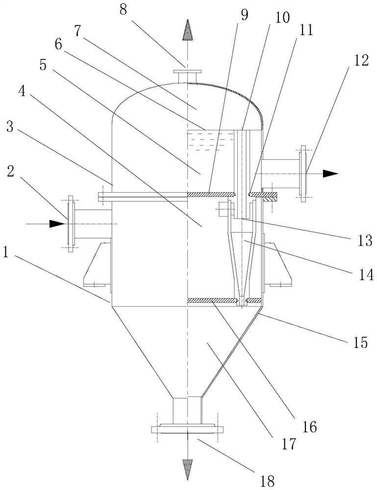
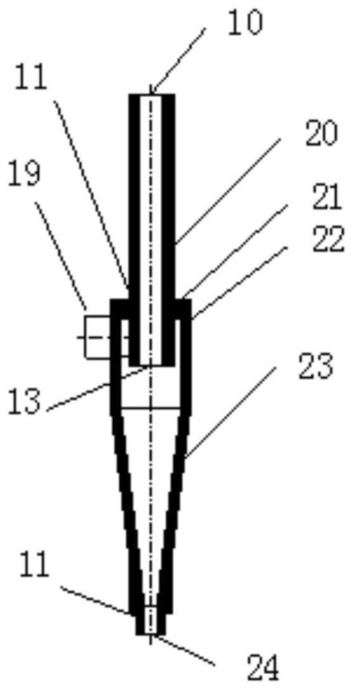
[0028] In order to express the structural advantages of this natural gas hydrate separation device more clearly, the following combination Figure 1-2 Further explain the functional characteristics of this device.

[0029] Such as figure 1 with figure 2 As shown, the natural gas hydrate separation equipment includes an upper cylinder body 3, a lower cylinder body 1, and one or more parallel cyclone separation pipes 14 arranged inside the joint space of the upper cylinder body 3 and the lower cylinder body 1, and the joint space The interior is divided into three chambers from top to bottom by the upper partition 9 and the lower partition 16, namely the overflow chamber, the feeding chamber 4 and the sand collection chamber 17. The upper and lower cylinders are connected by flanges to form a mating space. The upper partition 9 is welded to the lower end of the upper cylinder 3 . The lower partition 16 is welded on the cylinder inner wall of the lower cylinder 1 . An overf...


PUM


Abstract

The invention provides natural gas hydrate separation equipment and process. The separation equipment comprises one or more cyclone separation pipes, an upper barrel and a lower barrel, wherein the upper barrel and lower barrel form a feeding cavity, an overflow cavity and a sand collecting cavity through partition plates, overflow outlets of the cyclone separation pipes communicate with the overflow cavity, a feeding port is located in the feeding cavity, an underflow opening communicates with the sand collecting cavity, natural gas hydrate extraction slurry enters the feeding cavity througha feeding pipe opening, natural gas and natural gas hydrate are separated through the cyclone separation pipes, the natural gas, the natural gas hydrate and a part of water are discharged into the overflow cavity through an overflow pipe, the natural gas enters a natural gas collecting pipe through an exhaust pipe opening, the natural gas hydrate slurry enters a natural gas hydrate slurry collecting pipe through a discharge pipe opening, and sand and a part of water are discharged into the sand collecting cavity through the underflow opening and discharged into water through the sand discharging pipe opening. According to the natural gas hydrate separation equipment and process, the separation equipment is simple in structure and process, the cyclone separation pipes can be operated in a multi-pipe parallel connection mode and can be flexibly replaced, and the requirement for sand removal of natural gas hydrate extraction slurry is met.

Description

technical field [0001] The invention belongs to the technical field of exploitation of natural gas hydrate resources, in particular to sand removal of natural gas hydrate in the exploitation process of natural gas hydrate solid fluidization method. Background technique [0002] Natural gas hydrate is a new energy source with huge reserves. It is widely distributed in the deep seabed and land permafrost. It is a clathrate hydrate formed by the combination of methane and other hydrocarbon gases and water. Because it mainly appears in a dispersed form on the seabed, it is weakly cemented with sediment, non-diagenetic, and the stability of the ore layer is poor, so there are big problems in conventional mining methods. Patent No. CN103628844A proposes a solid-state fluidized mining process. Through in-situ mining, the hydrate particles are broken, without changing the temperature and pressure of the seabed, and the lifting and self-decomposition of the hydrate slurry is realized...

Claims


Application Information

Patent Timeline
IPC IPC(8): E21B43/36E21B43/40
CPCE21B43/36E21B43/40
Inventor 袁惠新钱钰琛付双成
Owner CHANGZHOU UNIV
Learn More