High-pressure gas flow rapid pressure reduction fairing device and method

A technology of rectification device and gas flow, which is applied in the direction of jet propulsion device, rocket engine device, machine/engine, etc., and can solve the requirement that the space occupied by the rectification device is not harsh, the pressure is high, and it cannot meet the rapid decompression of engine gas, Rectification and other issues

Active Publication Date: 2021-03-19
XIAN AEROSPACE PROPULSION INST
View PDF6 Cites 1 Cited by
  • Summary
  • Abstract
  • Description
  • Claims
  • Application Information

AI Technical Summary

Problems solved by technology

[0004] Referring to the domestic and foreign documents related to the scheme, the flow medium suitable for the existing rectification device products is mostly air medium with low speed, normal temperature and normal pressure. The design purpose of the scheme is equal pressure rectification, although the rectification device will bring a certain total pressure loss, but the decompression of the airflow is not the main purpose, because the existing required volume flow rate is relatively small, the requirements for the space occupied by the rectification device are not strict
However, the gas produced by the joint test of the supplementary combustion cycle semi-system has the characteristics of large flow rate, high temperature (above 600K), high pressure (above 20MPa), complex components, and variable flow. The current rectification methods and devices cannot meet the requirements. Requirements for rapid decompression and rectification of engine gas

Method used


Image

  • High-pressure gas flow rapid pressure reduction fairing device and method
  • High-pressure gas flow rapid pressure reduction fairing device and method
  • High-pressure gas flow rapid pressure reduction fairing device and method

Examples


Embodiment 1

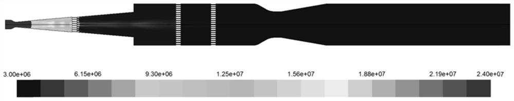
[0044] The decompression and rectification device has been successfully applied in the semi-system test run of a conventional afterburning engine, the theoretical temperature of the upstream gas is 750K, and the total pressure is 24MPa.

[0045] figure 2 is the pressure change of the flow field in the decompression rectification device under the above conditions. Depend on figure 2 It can be seen that the gas flow forms a primary shock wave in the front part of the supersonic shock wave section 2, the total gas pressure before the shock wave is 24MPa, and the total gas pressure after the shock wave is 14MPa; behind the porous damping plate 3, a secondary shock wave is generated, and the gas flow The total pressure dropped for the second time. The total gas pressure before the porous damping plate 3 was 14MPa, and after the porous damping plate 3, the total pressure of the gas dropped to 3-4MPa; the total pressure of the gas flow at the outlet flange 11 dropped to 3MPa.

[...


PUM


Abstract

The invention provides a high-pressure gas flow rapid pressure reduction fairing device and method. The high-pressure gas flow rapid pressure reduction fairing device is of a revolving body structure,and sequentially comprises an inlet flange (1), a supersonic speed shock wave section (2), a straight section (5), a convergence section (10) and an outlet flange (11) along the gas flow direction. After a gas flow enters the device, the total pressure is rapidly reduced through two times of shock waves, and after multiple times of fairing treatment, the gas flow speed and uniformity are accurately controlled. The flow quality of fuel gas can be comprehensively improved, and proper gas flow inlet parameter conditions are provided for non-toxic treatment of downstream fuel gas.

Description

technical field [0001] The invention belongs to the technical field of detoxification treatment of harmful gases, and relates to a pretreatment method for detoxification of harmful gases, in particular to a device and method for rapid decompression and rectification of high-pressure gas flow. Background technique [0002] Normal temperature propellants such as unsymmetrical dimethylhydrazine and dinitrogen tetroxide are widely used in aerospace propulsion systems, and have the advantages of reliable ignition, stable combustion, and convenient storage and transportation. A large amount of incompletely decomposed oxygen-enriched gas will be produced during the research test of this type of engine. Due to the high toxicity of this type of propellant and its incompletely decomposed products, it is necessary to use combustion gas during the semi-system test of the afterburning cycle engine. Methods It is non-toxic and real-time treatment to meet the emission requirements of green...

Claims


Application Information

Patent Timeline
Patent Type & Authority Applications(China)
IPC IPC(8): F02K9/60
CPCF02K9/60
Inventor 肖虹李悦李龙飞房喜荣李小平熊剑刘昭宇唐敏
Owner XIAN AEROSPACE PROPULSION INST
Why Eureka
Try Eureka