Instant pipeline heater and manufacturing method thereof
A technology of a pipeline heater and a manufacturing method, which is applied in the directions of water heaters, fluid heaters, manufacturing tools, etc., can solve the problems of difficult coiling process, affecting heat transfer effect, easy to produce scale, etc., and achieves simple structure and simple process. , The effect of not easy to scale
- Summary
- Abstract
- Description
- Claims
- Application Information
AI Technical Summary
Problems solved by technology
Method used
Image
Examples
Embodiment 1
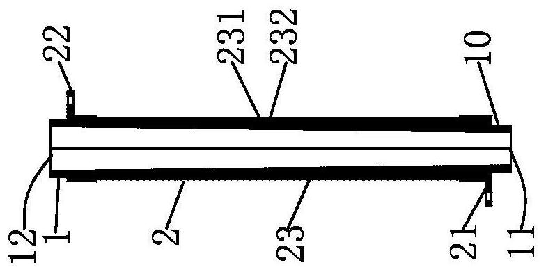
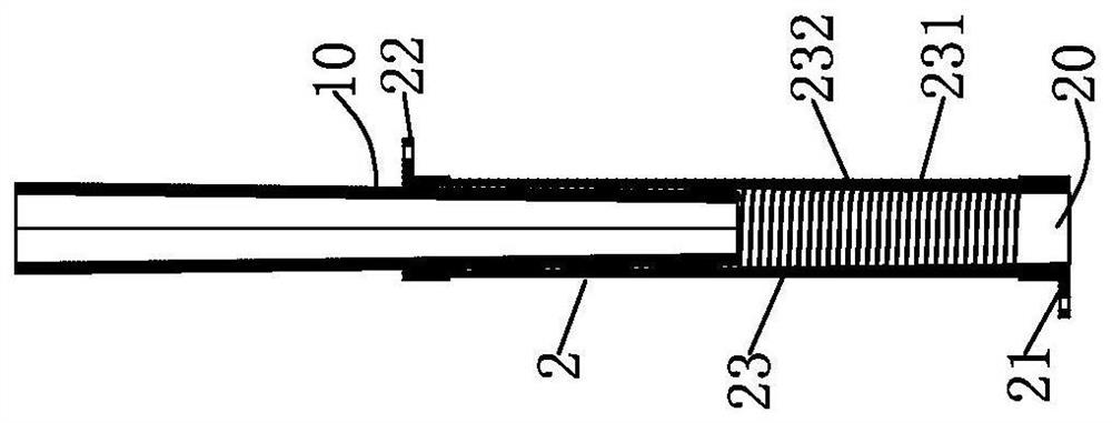
[0032] Embodiment 1: as figure 1 and figure 2 As shown, an instant heating pipe heater includes a water pipe 1, and is characterized in that it also includes a tubular heating element 2 that is energized and generates heat. The tubular heating element includes a first conductive end 21, a second conductive end 22 and The tubular heating wall 23, the first conductive end 21 and the second conductive end 22 are respectively connected to the tubular heating wall 23, the tubular heating wall 23 is provided with a gap 231, and the gap 231 divides the tubular heating wall 23 It is a energized heating line 232 connected between the first conductive end 21 and the second conductive end 22 , and the tubular heating element 2 is nested and closely attached to the outer wall of the water pipe 1 . This type of instant pipe heater, the tubular heating element 2 that is energized and heated is directly sleeved and closely attached to the outer wall of the water pipe 1, and the water pipe ...
Embodiment 2
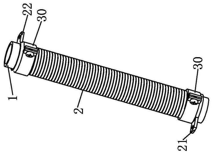
[0044] Embodiment 2: as image 3 As shown, this embodiment is similar to Embodiment 1, the difference is: the outer wall of the water pipe 1 is a cylindrical section with the same outer diameter, the inner cavity of the tubular heating element 2 is a cylindrical cavity, and the cylindrical cavity The shape of the cavity is adapted to the shape of the cylindrical section, the tubular heating element 2 is sleeved on the water pipe 1, and the two ends of the tubular heating element 2 are provided with fixing parts 30, the water pipe 1 and the tubular The heating element 2 is connected by a fixing member 30; the working principle of this embodiment is similar to that of the first embodiment, and will not be described in detail here.
Embodiment 3
[0045] Embodiment 3: as Figure 4 As shown, this embodiment is similar to Embodiment 1, the difference is: the outer wall of the water pipe 1 is a cylindrical section with the same outer diameter, the inner cavity of the tubular heating element 2 is a cylindrical cavity, and the cylindrical cavity The shape of the cavity is adapted to the shape of the cylindrical section, the inner two ends of the tubular heating element are provided with internal threads 40, the outer wall of the water pipe is provided with corresponding external threads 50, the water pipe 1 and the tubular heating The body 2 is threaded; the working principle of this embodiment is similar to that of embodiment 1, and will not be described in detail here.
PUM
| Property | Measurement | Unit |
|---|---|---|
| Outer diameter | aaaaa | aaaaa |
| Thickness | aaaaa | aaaaa |
| Tube outer diameter | aaaaa | aaaaa |
Abstract
Description
Claims
Application Information
 - R&D
- Intellectual Property
- Life Sciences
- Materials
- Tech Scout
- Unparalleled Data Quality
- Higher Quality Content
- 60% Fewer Hallucinations
Browse by: Latest US Patents, China's latest patents, Technical Efficacy Thesaurus, Application Domain, Technology Topic, Popular Technical Reports.
© 2025 PatSnap. All rights reserved.Legal|Privacy policy|Modern Slavery Act Transparency Statement|Sitemap|About US| Contact US: help@patsnap.com


