Infrared food detector

A detector and food technology, applied in the direction of color/spectral characteristic measurement, etc., can solve the problems affecting the smooth flow of the production line, interfering with the normal operation of the assembly line, and affecting the food production efficiency, so as to enhance the inspection efficiency, avoid relative slippage, and maintain operation efficiency effect

Pending Publication Date: 2021-03-19
左延鹏
View PDF0 Cites 4 Cited by
  • Summary
  • Abstract
  • Description
  • Claims
  • Application Information

AI Technical Summary

Problems solved by technology

[0003] When the infrared food detector is running, it needs to place the food in a fixed position of the detector, wait for the infrared spectrum image displayed in it and conduct professional technical analysis on it to determine the detection results of each component in the food, and in the food During the production process of the assembly line, the detection steps performed by the infrared detector interfere with the normal operation of the assembly line, and require an additional detection area, which also affects the food production efficiency of the assembly line
[0004] There are also some technical solutions for infrared food detection in the prior art. For example, a Chinese patent with application number 2019111770934 discloses an infrared food safety detection device, including a casing, which is provided with an inlet cavity , the left end wall of the feeding chamber is provided with a feeding mechanism, the left end wall of the feeding mechanism is provided with a driving mechanism that provides power to the devi

Method used


Image

  • Infrared food detector
  • Infrared food detector
  • Infrared food detector

Examples


Embodiment approach

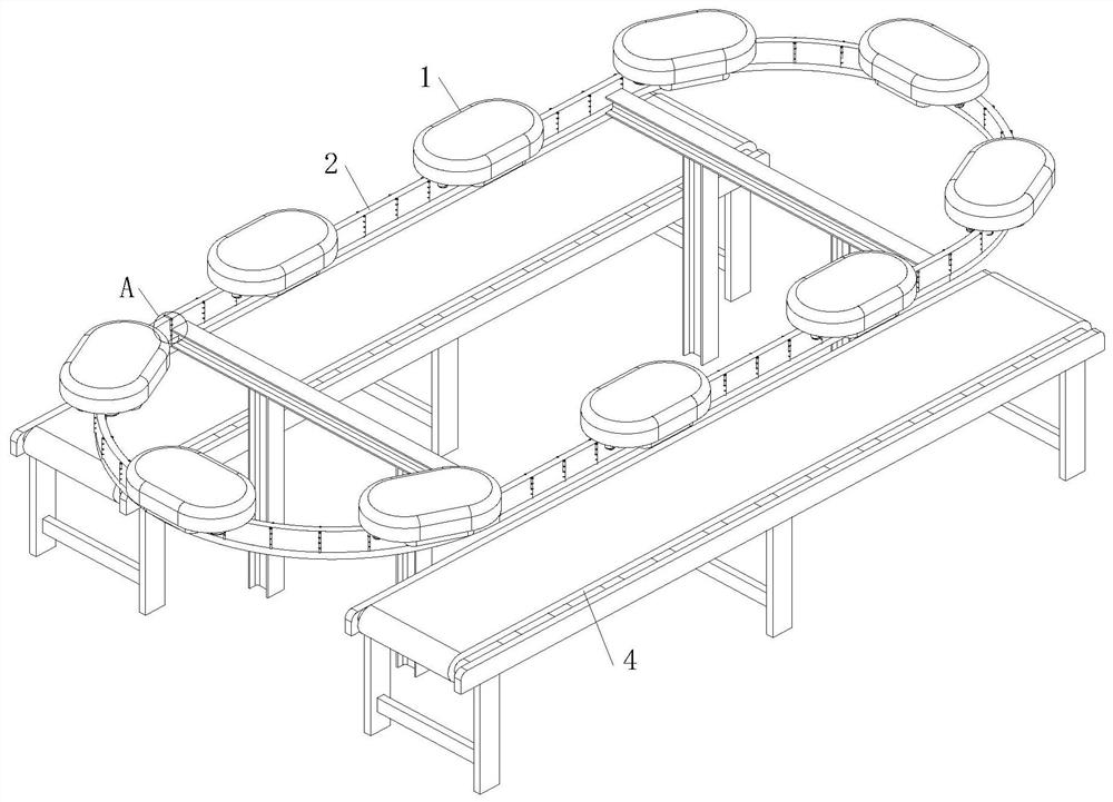
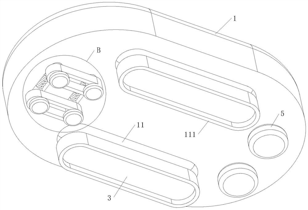
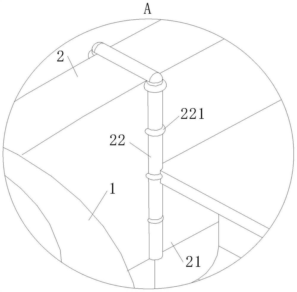
[0029] As an embodiment of the present invention, a plurality of sliding bodies 1 are installed on the detection track 2, and the bodies 1 are respectively located on the detection tracks 2 above the two conveyor belts 4, and the distance between the bodies 1 is its own distance. Length; the food to be detected on the conveyor belt 4 is placed together in contact with each other, and the body 1 used for infrared detection loses the detection function of the food in the arc bending area on the detection track 2, and then cannot reach It has a complete detection effect on food; multiple bodies 1 arranged on the detection track 2 cooperate with the two conveyor belts 4 under the circular detection track 2, and the infrared light source in it is 3 The food on the conveyor belt 4 is detected at intervals, and the food on the two conveyor belts 4 below the detection track 2 is controlled to be detected by the infrared light source 3 on the body 1 at intervals, which prevents the body...


PUM


Abstract

The invention relates to the technical field of food detection and particularly relates to an infrared food detector which comprises a machine body, a detection rail and a controller. Due to the factthat when the infrared food detector operates, food needs to be placed in a fixed position of the detector, professional technical analysis is conducted on infrared spectrum images displayed in the infrared food detector to determine detection results of all components in the food, and in the production process of a food assembly line, detection efficiency of the food detector is greatly improved;the detection step performed by the infrared detector interferes with the normal operation of the assembly line, an additional detection area needs to be occupied, and assembly line type food production efficiency further is influenced; Therefore, through the arranged detection rail, the infrared food detector and food on the conveying belt are in a relatively static state, stable operation of the food on the conveying belt in the infrared detection process is further achieved, operation efficiency of the infrared food detector on an assembly line type food production line is maintained, andtherefore the application effect of the infrared food detector is improved.

Description

technical field [0001] The invention relates to the technical field of food detection, in particular to an infrared food detector. Background technique [0002] With the improvement of people's living standards, there are more and more types of food in life, and the resulting food safety issues have become a hot spot of social concern. When infrared spectroscopy is applied to food testing, certain food substances in molecules The vibration or rotation frequency of a group can be consistent with the frequency of infrared light, its molecules absorb energy, and jump from the original ground state vibration energy level to a higher energy vibration energy level, where the light of the wavelength is absorbed by the substance, and the The absorption of infrared light by molecules is recorded by an instrument to obtain an infrared spectrogram. The infrared spectrogram usually uses the wavelength λ or wave number σ as the abscissa to indicate the position of the absorption peak, an...

Claims


Application Information

Patent Timeline
IPC IPC(8): G01N21/35
CPCG01N21/35
Inventor 左延鹏秦松
Owner 左延鹏
Why Eureka
Try Eureka