Distribution network feeder line constant value checking table

A fixed value verification and line technology, which is applied in the direction of circuit breaker testing, measuring devices, instruments, etc., can solve the problems of no distribution network operation, affecting the verification effect, and low reliability

CN112526258AInactive Publication Date: 2021-03-19GUANGDONG POWER GRID CO LTD +1
8 Cites 0 Cited by

Patent Information

Authority / Receiving Office
CN · China
Patent Type
Applications(China)
Current Assignee / Owner
Publication Date
2021-03-19
Estimated Expiration
Not applicable · inactive patent

Smart Images

  • Figure 1
    Figure 1
  • Figure 2
    Figure 2
  • Figure 3
    Figure 3
Patent Text Reader

Abstract

The embodiment of the invention discloses a distribution network feeder line constant value calibration table. The distribution network feeder line constant value calibration table comprises at leasttwo analog circuit breakers, at least two measurement and control terminals in one-to-one correspondence with the at least two analog circuit breakers, an analog main station, a three-phase three-wirecurrent and voltage input terminal, a fault wiring terminal and an opening and closing indication module, wherein the at least two analog circuit breakers are connected in series in a line, one end of each analog circuit breaker inputs bus current and bus voltage through the line connected with the three-phase three-wire current and voltage input terminal, and the other end of each analog circuitbreaker inputs fault current and / or fault voltage through the fault wiring terminal; the measurement and control terminals are electrically connected with the corresponding analog circuit breakers and are used for controlling the switching-on and switching-off operations of the analog circuit breakers; the simulation main station is in communication connection with the measurement and control terminals; and the opening and closing indication module is electrically connected with the measurement and control terminals. According to the distribution network feeder line constant value verification platform, the reliability of constant value verification can be improved, and a relatively good verification effect is achieved.
Need to check novelty before this filing date? Find Prior Art

Description

technical field

[0001] The embodiment of the present invention relates to line fixed value verification technology, in particular to a distribution network feeder fixed value verification platform. Background technique

[0002] Distribution network automation technology is an important means of distribution management. Under the background of the rapid development of distribution network, in order to shorten the power outage time of users, and to locate and repair faults more quickly, it has become normal to change the line setting configuration. In response to various large-scale user power dedicated lines, choosing a more efficient fixed value configuration scheme will become a future trend, making the verification of the fixed value of distribution network feeder an important research content.

[0003] At present, the existing distribution network feeder fixed value verification method is usually to manually calculate the fixed value and then directly set the fixed value ...

Examples

Embodiment 1

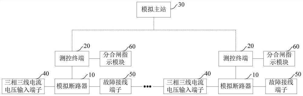
[0025] figure 1 It is a structural block diagram of a distribution network feeder fixed value verification platform provided by Embodiment 1 of the present invention. This embodiment is applicable to situations such as distribution network feeder fixed value verification. The distribution network feeder fixed value verification platform includes: at least Two analog circuit breakers 10, at least two measurement and control terminals 20 corresponding to at least two analog circuit breakers 10, an analog master station 30, a three-phase three-wire current and voltage input terminal 40, a fault connection terminal 50 and an opening and closing indication module 60.

[0026] Among them, at least two analog circuit breakers 10 are connected in series in the line, one end of the analog circuit breaker 10 inputs the bus current and bus voltage through the line connected to the three-phase three-wire current and voltage input terminal 40, and the other end of the analog circuit breake...

Embodiment 2

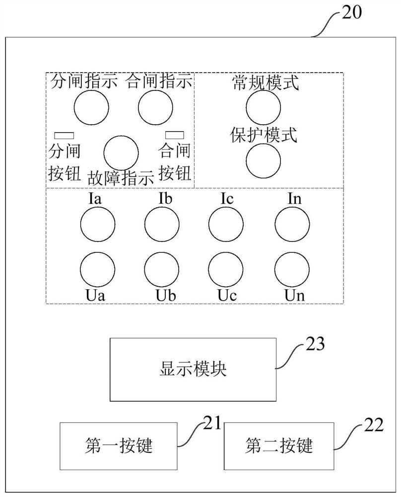
[0032] figure 2 It is a schematic structural diagram of a measurement and control terminal provided in Embodiment 2 of the present invention. This embodiment is based on Embodiment 1, combining figure 1 and figure 2 Optionally, the panel of the measurement and control terminal 20 is provided with a first button 21 and a second button 22, the first button 21 is used to adjust the fixed value of voltage and current, and the second button 22 is used to adjust the operating time of the circuit breaker.

[0033] Among them, the first button 21 and the second button 22 are both arranged on the panel of the measurement and control terminal 20, which is convenient for simulating that the circuit breaker 10 does not operate or the phenomenon of over-level tripping occurs when the above-mentioned fault current and / or fault voltage is input, that is, the set When there is a problem with the fixed value of voltage and current and the operating time of the simulated circuit breaker 10, ...