Isolated container interior glazing equipment for ceramic processing

A ceramic processing and isolation technology, which is applied to the field of glazing equipment inside an isolation container for ceramic processing, can solve the problems of lack of protective measures, low efficiency, glaze drifting around, etc., to prevent glaze from drifting out and high work efficiency. Effect

Active Publication Date: 2021-03-23
潮州市嘉诺陶瓷有限公司
View PDF11 Cites 7 Cited by
  • Summary
  • Abstract
  • Description
  • Claims
  • Application Information

AI Technical Summary

Problems solved by technology

[0005] In order to overcome the shortcomings that the staff can only glaze one ceramic at a time, the efficiency is low. Secondly, there are no protective measures around, and the glaze will be scattered around, affecting the surrounding environment. The technical problem to be solved is: provide a working efficiency Glazing equipment for the interior of isolated containers for ceramic processing that is high and does not affect the surrounding environment

Method used


Image

  • Isolated container interior glazing equipment for ceramic processing
  • Isolated container interior glazing equipment for ceramic processing
  • Isolated container interior glazing equipment for ceramic processing

Examples


Embodiment 1

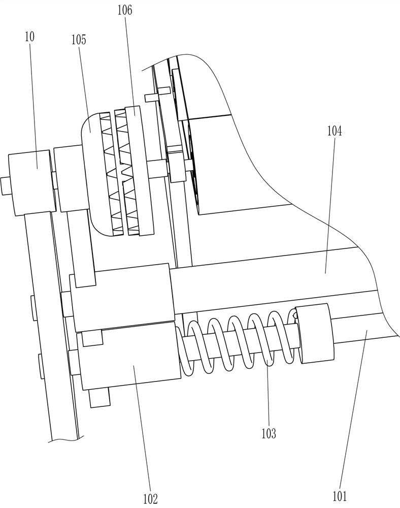
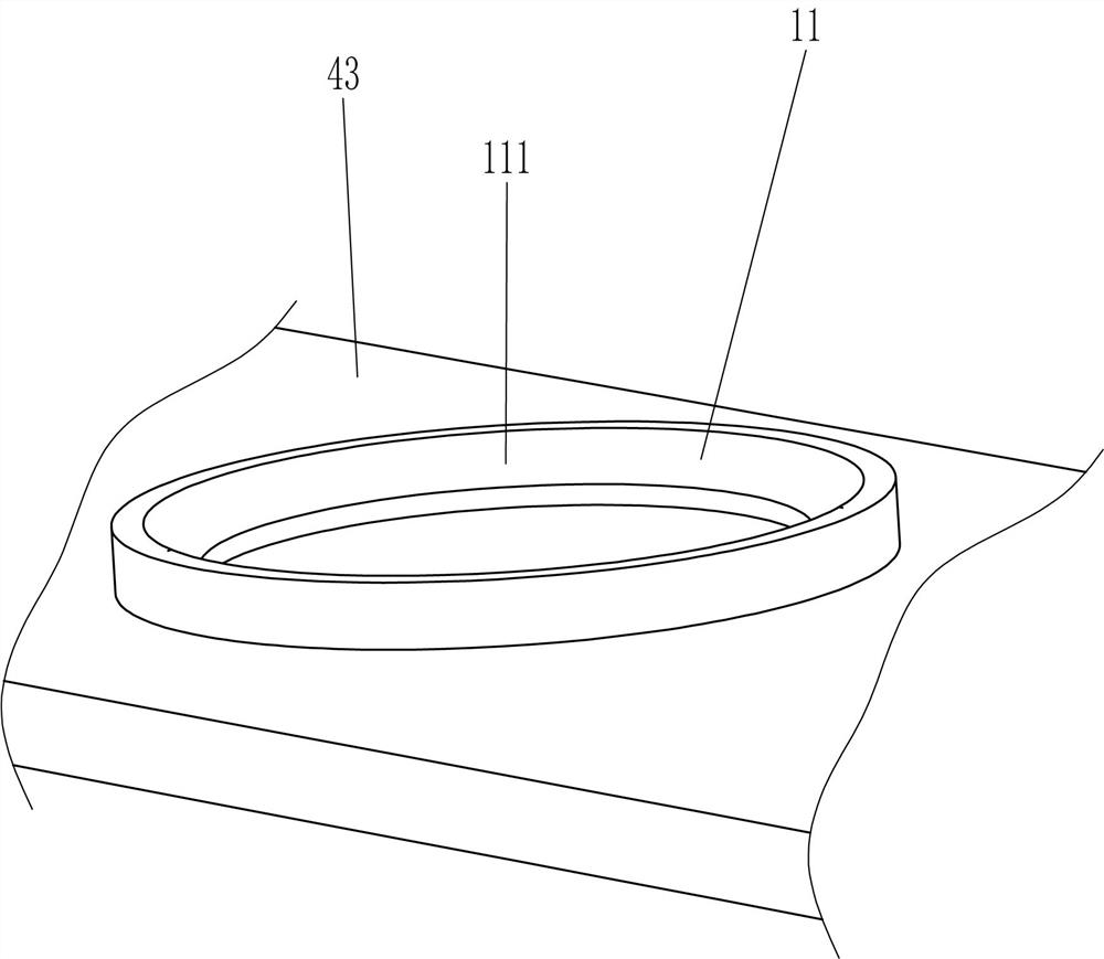
[0036] A kind of glazing equipment inside an isolated container for ceramic processing, such as Figure 1-6As shown, it includes installation platform 1, roller frame 41, conveyor belt 42, placement plate 43, driving mechanism 5, moving mechanism 6, booster mechanism 7 and spraying mechanism 8, and rollers are installed on the left and right sides of the top of installation platform 1 Frame 41, a conveyor belt 42 is wound around the two roller frames 41, and the outside of the conveyor belt 42 is connected with a placement plate 43 at even intervals. A spraying mechanism 8 is installed on the mechanism 6 , and a booster mechanism 7 is installed on the rear side of the mounting table 1 .

[0037] When it is necessary to glaze the interior of the ceramics, the staff will neatly place a plurality of ceramics on the placement plate 43, then press the main power switch to power on the device, and then press the start key, which sends a signal to control After receiving the signal,...

Embodiment 2

[0047] On the basis of Example 1, such as image 3 , Figure 6 , Figure 7 , Figure 8 and Figure 9 As shown, the leak-proof mechanism 9 is also included, and the leak-proof mechanism 9 includes a bracket 91, a second guide sleeve 92, a second guide rod 93, a fourth spring 94, a hinged cover plate 95 and an elastic cord 96, and the bottom of the cylinder body 81 Connected with a bracket 91, the bracket 91 is connected with a second guide sleeve 92, the second guide sleeve 92 is slidably provided with a second guide rod 93, the second guide rod 93 runs through the protective cover 88, and the second guide rod 93 is covered with The fourth spring 94, the two ends of the fourth spring 94 are respectively connected with the second guide sleeve 92 and the second guide rod 93, the bottom end of the second guide rod 93 is rotatably connected with a hinged cover 95, the hinged cover 95 is connected with the nozzle 86 In contact, an elastic cord 96 is connected between the hinged ...


PUM


Abstract

The invention relates to glazing equipment, in particular to isolated container interior glazing equipment for ceramic processing. The technical aim to be achieved is to provide the isolated containerinterior glazing equipment for ceramic processing. The equipment is high in working efficiency and does not influence the surrounding environment. According to the technical scheme, the isolated container interior glazing equipment for ceramic processing comprises a mounting table, roller frames and a conveying belt. The roller frames are rotationally mounted at the two sides of the top of the mounting table; and the conveying belt is arranged between the roller frames in a winding manner. Through cooperation of a moving mechanism and a spraying mechanism, multiple pieces of ceramic can be glazed at a time, the working efficiency is high, the spraying mechanism can cover glaze, the glaze is prevented from drifting out, and the influence on the surrounding environment is avoided; and a protective cover can be in close contact with the ceramic through a fitting mechanism, so that the glaze is further prevented from drifting out.

Description

technical field [0001] The invention relates to a glazing device, in particular to a glazing device inside an isolated container for ceramic processing. Background technique [0002] Ceramic is a living vessel that can be used to hold meals and some other foods. It is mainly made of clay. When producing ceramics, it is necessary to glaze the interior of the ceramics to make the interior smoother and improve the performance of the ceramics. , is one of the important steps. [0003] At present, the staff usually hold the spray gun to spray the glaze into the interior of the ceramics for glazing. The staff can only glaze one ceramic at a time, which is inefficient. Secondly, there are no protective measures around, and the glaze will float around, affecting In the surrounding environment, the staff may inhale some floating glaze, which will affect the health of the staff. [0004] We design a device with high working efficiency and will not affect the surrounding environment ...

Claims


Application Information

Patent Timeline
Patent Type & Authority Applications(China)
IPC IPC(8): B28B11/04B28B17/00
CPCB28B11/044B28B11/048B28B17/00
Inventor 孙万彪
Owner 潮州市嘉诺陶瓷有限公司
Why Eureka
Try Eureka